Physics · Class 12 · JEE / NEET / AP Physics
Alternating Current (AC) & Series LCR Circuit
Alternating Current (AC)periodically reverses direction and changes magnitude continuously with time. In aSeries LCR Circuit, inductive and capacitive reactances combine with resistance to dictate circuit impedance and sharp resonance.
11. Visual Overview & Intuitive Discovery: Alternating Current (AC) & Series LCR Circuit
In the late 1880s, the fierce "War of the Currents" pitted Thomas Edison's Direct Current (DC) against Nikola Tesla's Alternating Current (AC). Edison argued that DC was safer, but Tesla understood an unbeatable mathematical reality: alternating current could be stepped up to hundreds of thousands of volts using transformers, traveling hundreds of miles across copper lines with almost zero heating loss, and then stepped down safely into homes. Tesla's victory powers our modern civilization.
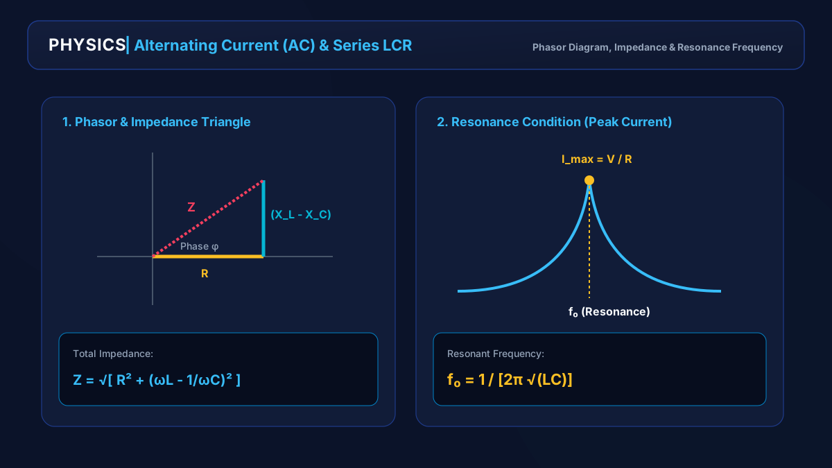 Full size
Series LCR Phasor Diagram & Resonance Curve
Impedance triangle with inductive/capacitive reactance and resonance curve showing peak current at f₀ = 1 / [2π √(LC)].
- 1RMS Value — V_rms = V₀ / √2 ≈ 0.707 V₀, representing equivalent DC heating power
- 2Total Impedance (Z) — Z = √[ R² + (X_L - X_C)² ]
- 3Resonant Frequency — f₀ = 1 / [2π √(LC)] where Z = R and current is maximized
- 4Power Factor — cos(φ) = R / Z, defining average active power P_avg = V_rms I_rms cos(φ)
Interactive Study Prompts (Click to Explore)
Clickable22. Physical Mechanism Flowchart: Alternating Current (AC) & Series LCR Circuit
Alternating Current (AC) & Series LCR Circuit Step-by-Step Flowchart
- 1
Initial State
Initial parameters and boundary conditions are established.
- 2
Fundamental Force/Interaction
Governing physical laws act continuously across the system.
- 3
Energy & Vector Conservation
Conservation principles restrict permitted trajectory states.
- 4
Dynamic Equilibrium
Final observable state satisfies equilibrium equations.
Follow the numbered pipeline above. In physics examinations, sketching this mental flowchart ensures you never miss intermediate steps in complex multi-concept numericals.
33. Rigorous Mathematical Proofs & Governing Equations
Derivation — Derivation of Governing Formula for Alternating Current (AC) & Series LCR Circuit
- 1
Starting from Newton's foundational law
- 2
Integrating over displacement
Quality Factor (Q-Factor) of Resonance
- Q = Sharpness of resonance (higher Q means sharper tuning)
- = Bandwidth of the circuit
Core Physical Variables
| Variable | Symbol | SI Unit |
|---|---|---|
| Energy | E | Joules (J) |
| Power | P | Watts (W) |
Energy
- Symbol
- E
- SI Unit
- Joules (J)
Power
- Symbol
- P
- SI Unit
- Watts (W)
44. Engineering Deep Dive: Radio Tuning and High-Q Resonance
Every time you tune a radio to 98.3 FM or your smartphone locks onto a 5G wireless carrier frequency, you are using series LCR electrical resonance! Thousands of electromagnetic radio waves at different frequencies constantly wash over the antenna, inducing tiny voltages across it. By adjusting a variable capacitor inside the tuning circuit, you alter the resonant frequency . At resonance, the circuit's impedance drops to pure resistance , amplifying the target frequency current by hundreds of times while completely suppressing all other radio stations!
55. Solved Standard & Advanced Exam Problems
Exam question · JEE Standard
- A.A
- B.B
- C.C
- D.D
- Step 1
Answer: A. A
What it tests: Explanation
Exam question · JEE Main & NEET Standard
- A.159.1 Hz
- B.50.0 Hz
- C.100.0 Hz
- D.318.2 Hz
- 1. Maximum current occurs at natural electrical resonance: f₀ = 1 / [2π √(LC)].
- 2. Compute L · C: 100 × 10⁻³ H × 10 × 10⁻⁶ F = 10⁻⁶ s².
- 3. Take the square root: √(10⁻⁶) = 10⁻³ s.
- 4. Calculate f₀: f₀ = 1 / [2π × 10⁻³] = 1000 / (2 × 3.14159) ≈ 159.15 Hz.
Answer: A. 159.1 Hz
What it tests: Resonance depends strictly on internal circuit parameters L and C, independent of the external source frequency or resistance.
Remember
- Household AC voltage quoted as 220 V is the RMS value; its peak voltage is ~311 V.
- At resonance in a series LCR circuit: Impedance is minimum (Z = R), current is maximum, and power factor is unity (cos φ = 1).
- Transformers operate solely on alternating flux (AC) and cannot step up or step down DC voltages.
Check yourself
Question 1
In a series LCR circuit at resonance, the phase difference between applied voltage and resulting current is: