Physics · JEE Main, NEET
Alternating Current
190 practice questions with a worked solution for each. Tap an option to see instantly if you are right.
139MCQ51Numerical45With diagram
- 1In a series LCR circuit with , , the resonant angular frequency is:JEE Main/MCQ/Medium
- 2In an AC circuit, voltage and current . Power factor is:NEET/MCQ/Medium
- 3In a series LCR circuit, . Quality factor of the circuit is:JEE Main/MCQ/Medium
- 4The electric current in the circuit is given as . The r.m.s current for the period to is .JEE Main/MCQ/Medium/Alternating Current, Voltage and Power
- 5An inductor of reactance , a capacitor of reactance , and a resistor of resistance are connected in series with an AC source of 10 V , 50 Hz. Average power dissipated by the circuit is ________ W.JEE Main/Numerical/Medium/Alternating Current, Voltage and Power
- 6An ac current is represented as
The r.m.s value of the current isJEE Main/MCQ/Medium/Alternating Current, Voltage and Power - 7An alternating current is represented by the equation, ampere. The RMS value of current and the frequency of the given alternating current areJEE Main/MCQ/Medium/Alternating Current, Voltage and Power
- 8An electric bulb rated as is connected to an ac source of rms voltage 220 V. The peak value of current through the bulb is :JEE Main/MCQ/Medium/Alternating Current, Voltage and Power
- 9Given below are two statements : one is labelled as Assertion (A) and the other is labelled as Reason (R).
Assertion (A) : Choke coil is simply a coil having a large inductance but a small resistance. Choke coils are used with fluorescent mercury-tube fittings. If household electric power is directly connected to a mercury tube, the tube will be damaged.
Reason (R): By using the choke coil, the voltage across the tube is reduced by a factor \(\left(R / \sqrt{R^2+\omega^2 L^2}\right)\), where \(\omega\) is frequency of the supply across resistor \(R\) and inductor L . If the choke coil were not used, the voltage across the resistor would be the same as the applied voltage.
In the light of the above statements, choose the most appropriate answer from the options given below :JEE Main/MCQ/Medium/Alternating Current, Voltage and Power - 10An alternating current is given by . The r.m.s current will beJEE Main/MCQ/Medium/Alternating Current, Voltage and Power
- 11A alternating current at any instant is given by A. The value of the current is ________ A.JEE Main/Numerical/Medium/Alternating Current, Voltage and Power
- 12In an ac circuit, the instantaneous current is zero, when the instantaneous voltage is maximum. In this case, the source may be connected to :
A. pure inductor.
B. pure capacitor.
C. pure resistor.
D. combination of an inductor and capacitor.
Choose the correct answer from the options given below :JEE Main/MCQ/Medium/Alternating Current, Voltage and Power - 13A parallel plate capacitor has a capacitance . It is connected to ac supply with an angular frequency . The rms value of conduction current in the circuit and displacement current in the capacitor respectively are :JEE Main/MCQ/Medium/Alternating Current, Voltage and Power
- 14An AC voltage is applied to a series LCR circuit which drives a current . The average power dissipated is:JEE Main/MCQ/Medium/Alternating Current, Voltage and Power
- 15An alternating voltage volt is applied to a purely resistive load of . The time taken for the current to rise from half of the peak value to the peak value is:JEE Main/MCQ/Medium/Alternating Current, Voltage and Power
- 16In an a.c. circuit, voltage and current are given by: and respectively. The average power dissipated in one cycle is :JEE Main/MCQ/Medium/Alternating Current, Voltage and Power
- 17A capacitor of capacitance is connected to an alternating source of emf given by . The maximum value of current in the circuit is approximately equal to:JEE Main/MCQ/Medium/Alternating Current, Voltage and Power
- 18A series LCR circuit consists of . , and . The input voltage is . The amplitude of current, in the circuit, is _____ .JEE Main/Numerical/Medium/Alternating Current, Voltage and Power
- 19An alternating voltage source is connected across a pure inductor of . Inductive reactance in the circuit is:JEE Main/MCQ/Medium/Alternating Current, Voltage and Power
- 20An alternating emf is applied to a circuit containing an inductance of . If an a.c. ammeter is connected in the circuit, its reading will be :JEE Main/MCQ/Medium/Alternating Current, Voltage and Power
- 21The equation of current in a purely inductive circuit is . If the inductance is then the equation for the voltage across the inductor, will beJEE Main/MCQ/Medium/Alternating Current, Voltage and Power
- 22A direct current of and an alternating current of peak value flow through resistance of and respectively. The ratio of heat produced in the two resistances in same interval of time will be :JEE Main/MCQ/Medium/Alternating Current, Voltage and Power
- 23An inductor of , a capacitor of and a resistor of are connected in series with a ac source. If the current is in phase with the emf, the frequency of ac source will be ______.JEE Main/Numerical/Medium/Alternating Current, Voltage and Power
- 24A telegraph line of length has a capacity of and it carries an alternating current at kilo cycle per second. If minimum impedance is required, then the value of the inductance that needs to be introduced in series is _____ . (If )JEE Main/Numerical/Medium/Alternating Current, Voltage and Power
- 25The current flowing through an ac circuit is given by . How long will the current take to reach the peak value starting from zero?JEE Main/MCQ/Medium/Alternating Current, Voltage and Power
- 26A sinusoidal voltage volt is applied to a series LCR circuit in which and . The phase difference between the applied voltage and resultant current will beJEE Main/MCQ/Medium/Alternating Current, Voltage and Power
- 27Given below are two statements :
Statement-I: The reactance of an ac circuit is zero. It is possible that the circuit contains a capacitor and an inductor.
Statement-II: In ac circuit, the average power delivered by the source never becomes zero.
In the light of the above statements, choose the correct answer from the options given belowJEE Main/MCQ/Medium/Alternating Current, Voltage and Power - 28As shown in the figure an inductor of inductance is connected to an source of emf and frequency . The instantaneous voltage of the source is when the peak value of current is . The value of is _____ .
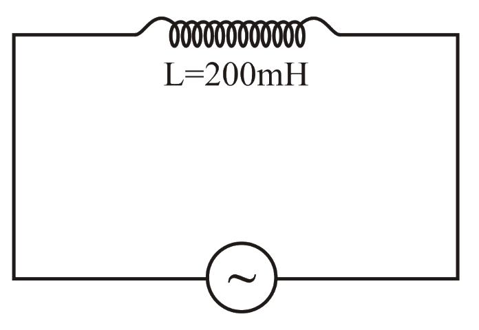 JEE Main/Numerical/Medium/Alternating Current, Voltage and Power/With diagram
- 29A resistance of is connected to a source of alternating current rated . Find the time taken by the current to change from its maximum value to the rms value :JEE Main/MCQ/Medium/Alternating Current, Voltage and Power
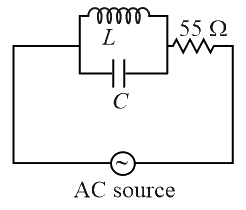
- 30At very high frequencies, the effective impedance of the given circuit will be _________
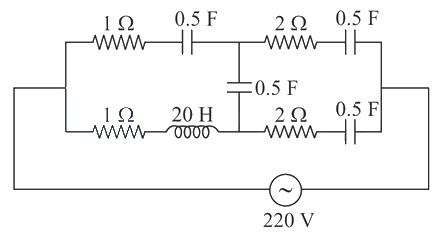 JEE Main/Numerical/Medium/Alternating Current, Voltage and Power/With diagram
- 31An AC circuit has an inductor and a resistor of resistance in series, such that . Now, a capacitor is added in series such that . the ratio of the new power factor with the old power factor of the circuit is . The value of isJEE Main/Numerical/Medium/Alternating Current, Voltage and Power
- 32The alternating current is given by, . The R.M.S. value of this current is __________ .JEE Main/Numerical/Medium/Alternating Current, Voltage and Power
- 33In the given circuit the source has . Considering the inductor and capacitor to be ideal, what will be the current flowing through the circuit?
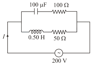 JEE Main/MCQ/Medium/Alternating Current, Voltage and Power/With diagram
- 34A resistance is connected across AC supply. The time taken by the current to change from its maximum value to the value is:JEE Main/MCQ/Medium/Alternating Current, Voltage and Power
- 35In a circuit consisting of a capacitance and a generator with alternating emf, and are the voltage and current. Correct phasor diagram for such circuit is
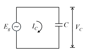 JEE Main/MCQ/Medium/Alternating Current, Voltage and Power/With diagram
- 36 voltage of frequency is applied to a parallel plate capacitor. The separation between the plates is and the area is . The amplitude of the oscillating displacement current for the applied voltage is JEE Main/MCQ/Medium/Alternating Current, Voltage and Power
- 37An source rated is connected to a resistor. The time taken by the current to change from its maximum to the rms value is :JEE Main/MCQ/Medium/Alternating Current, Voltage and Power
- 38What happens to the inductive reactance and the current in a purely inductive circuit if the frequency is halved ?JEE Main/MCQ/Medium/Alternating Current, Voltage and Power
- 39Match List-I with List-II List-i List-II a Phase difference between current and voltage in a purely resistive AC circuit i current leads
voltage b Phase difference between current and
voltage in a pure inductive AC circuit ii zero c Phase difference between current and
voltage in a pure capacitive AC circuit iii current lags
voltage d Phase difference between current and
voltage in an LCR series circuit iv Choose the most appropriate answer from the options given below :JEE Main/MCQ/Medium/Alternating Current, Voltage and Power - 40An current is given by
A hot wire ammeter will give a reading:JEE Main/MCQ/Medium/Alternating Current, Voltage and Power - 41Find the peak current and resonant frequency of the following circuit (as shown in figure).
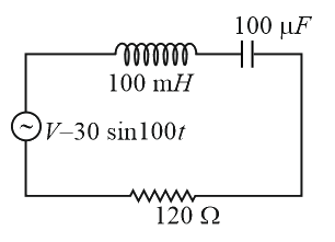 JEE Main/MCQ/Medium/Alternating Current, Voltage and Power/With diagram
- 42An alternating current is given by the equation . The rms current will be:JEE Main/MCQ/Medium/Alternating Current, Voltage and Power
- 43Match List I with List II. List I List II (a) Rectifier (i) Used either for stepping up or stepping down the A.C. voltage (b) Stabilizer (ii) Used to convert A.C. voltage into D.C. voltage (c) Transformer (iii) Used to remove any ripple in the rectified output voltage (d) Filter (iv) Used for constant output voltage even when the input voltage or load current change Choose the correct answer from the options given below:JEE Main/MCQ/Medium/Alternating Current, Voltage and Power
- 44A part of a complete circuit is shown in the figure. At some instant, the value of current I is and it is decreasing at a rate of . The value of the potential difference (in volts) at that instant is-
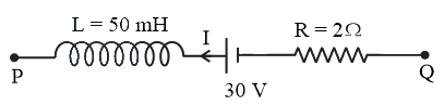 JEE Main/Numerical/Medium/Alternating Current, Voltage and Power/With diagram
- 45An alternating voltage volt is applied to a purely resistive load of . The time taken for the current to rise from half of the peak value to the peak value is:JEE Main/MCQ/Medium/Alternating Current, Voltage and Power
- 46
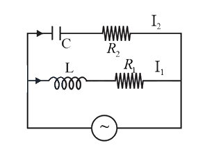
In the above circuit, and Current in path is and in path it is The voltage of volts. The phase difference between and is:JEE Main/MCQ/Medium/Alternating Current, Voltage and Power/With diagram - 47A series circuit containing an inductor a capacitor and a resistor is driven by an source of The energy dissipated in the circuit in is:JEE Main/MCQ/Medium/Alternating Current, Voltage and Power
- 48The AC voltage across a resistance can be measured using a:JEE Main/MCQ/Medium/Alternating Current, Voltage and Power
- 49A sinusoidal voltage is applied across a pure inductance of . The current through the coil is:JEE Main/MCQ/Medium/Alternating Current, Voltage and Power
- 50In an a.c. circuit the voltage applied is . The resulting current in the circuit is . The power consumption in the circuit is given byJEE Main/MCQ/Medium/Alternating Current, Voltage and Power
- 51A metal wire of linear mass density of is stretched with a tension of -wt between two rigid supports 1 metre apart. The wire passes at its middle point between the poles of a permanent magnet, and it vibrates in resonance when carrying an alternating current of frequency . The frequency of the alternating source isJEE Main/MCQ/Medium/Alternating Current, Voltage and Power
- 52A LCR series circuit driven with V at frequency Hz has resistance , an inductance with inductive reactance and capacitance with capacitive reactance . The power factor of the circuit is _______.JEE Main/MCQ/Medium/AC Circuits
- 53A series LCR circuit with , and is connected to a variable frequency a.c. source. The inductive reactance at resonant frequency is _______ .JEE Main/Numerical/Medium/AC Circuits
- 54An a.c. source of angular frequency is connected across a resistor and a capacitor in series. The current is observed as . Now the frequency of the source is changed to , (keeping the voltage unchanged) the current is found to be . The ratio of resistance to reactance at frequency isJEE Main/MCQ/Medium/AC Circuits
- 55An inductor of mH, capacitor of F and a resistor of are connected in series across an power supply V, Hz. The power factor of the given circuit is . The difference in the inductive reactance and capacitance reactance is . The value of is _____.JEE Main/Numerical/Medium/AC Circuits
- 56The figure given below shows an series circuit with two switches and . When switch is closed keeping open, the phase difference between the current and source voltage is and phase difference is when is closed keeping open. The value of is _______ H.
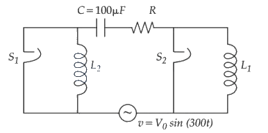 JEE Main/MCQ/Medium/AC Circuits/With diagram
- 57An inductor stores 16 J of magnetic field energy and dissipates 32 W of thermal energy due to its resistance when an a.c. current of 2 A (rms) and frequency 50 Hz flows through it. The ratio of inductive reactance to its resistance is . JEE Main/Numerical/Medium/AC Circuits
- 58Using a variable frequency a.c. voltage source the maximum current measured in the given LCR circuit is 50 mA for The values of and are shown in the figure. The capacitance of the capacitor (C) used is .
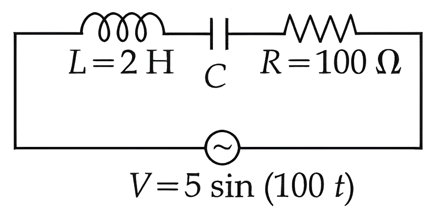 JEE Main/Numerical/Medium/AC Circuits/With diagram
- 59A capacitor is first charged fully with potential difference of and disconnected from the battery. The charged capacitor is connected across an inductor having inductance . In of the initial energy in the capacitor is transferred to the inductor. The value of is s.JEE Main/MCQ/Medium/AC Circuits
- 60For ac circuit shown in figure, and and the phase difference between and is . The input signal frequency is , where ' x ' is ______
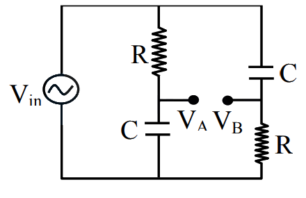 JEE Main/Numerical/Medium/AC Circuits/With diagram
- 61In a series LCR circuit, a resistor of , a capacitor of 25 nF and an inductor of 100 mH are used. For maximum current in the circuit, the angular frequency of the ac source is _____ radians .JEE Main/Numerical/Medium/AC Circuits
- 62A series LCR circuit is connected to an alternating source of emf E. The current amplitude at resonant frequency is . If the value of resistance R becomes twice of its initial value then amplitude of current at resonance will beJEE Main/MCQ/Medium/AC Circuits
- 63A capacitor of reactance and a resistor of resistance are connected in series with an ac source of peak value . The power dissipation in the circuit is ________ W.JEE Main/Numerical/Medium/AC Circuits
- 64An alternating emf volt is applied to a capacitor of , the rms value of current in the circuit is _____,JEE Main/Numerical/Medium/AC Circuits
- 65A coil of negligible resistance is connected in series with resistor across supply. A voltmeter reads across resistance. Inductance of the coil is :JEE Main/MCQ/Medium/AC Circuits
- 66A LCR circuit is at resonance for a capacitor , inductance and resistance . Now the value of resistance is halved keeping all other parameters same. The current amplitude at resonance will be now:JEE Main/MCQ/Medium/AC Circuits
- 67For a given series LCR circuit it is found that maximum current is drawn when value of variable capacitance is . If resistance of and inductor is being used in the given circuit. The frequency of ac source is ______ . (given )JEE Main/Numerical/Medium/AC Circuits
- 68When a voltage of is applied to an inductor, a current of flows through it. When an ac voltage of peak value is connected to inductor, its inductive reactance is found to be . The power dissipated in the circuit is _______ W.JEE Main/Numerical/Medium/AC Circuits
- 69Given below are two statements:
Statement I: In an LCR series circuit, current is maximum at resonance.
Statement II: Current in a purely resistive circuit can never be less than that in a series LCR circuit when connected to same voltage source.
In the light of the above statements, choose the correct from the options given below:JEE Main/MCQ/Medium/AC Circuits - 70A series LCR circuit is subjected to an ac signal of . If the voltage across the inductor is , then the current in this circuit is _____ .JEE Main/MCQ/Medium/AC Circuits
- 71An ac source is connected in given series LCR circuit. The rms potential difference across the capacitor of is _____V.
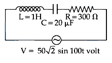 JEE Main/Numerical/Medium/AC Circuits/With diagram
- 72Match List I with List II
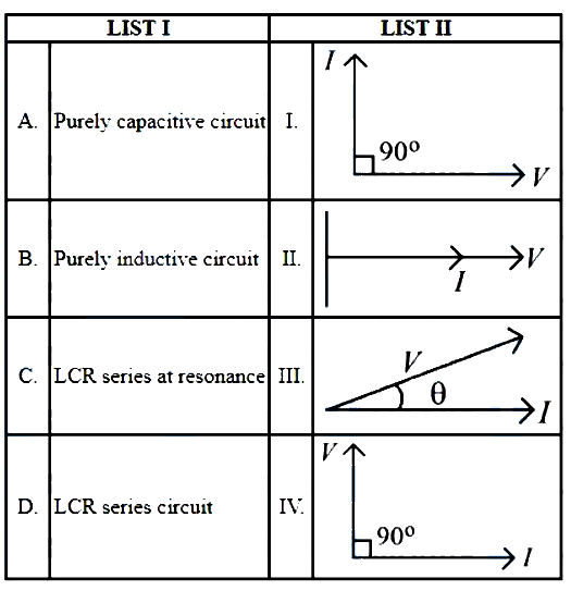
JEE Main/MCQ/Medium/AC Circuits/With diagram - 73In series LCR circuit, the capacitance is changed from to . To keep the resonance frequency unchanged, the new inductance should be :JEE Main/MCQ/Medium/AC Circuits
- 74In the given figure, the charge stored in capacitor, when points and are joined by a connecting wire is _______.
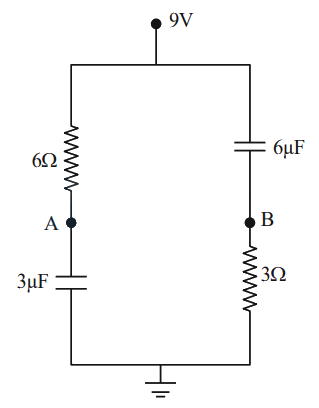 JEE Main/Numerical/Medium/AC Circuits/With diagram
- 75Given below are two statements:
Statement I : An AC circuit undergoes electrical resonance if it contains either a capacitor or an inductor.
Statement II: An AC circuit containing a pure capacitor or a pure inductor consumes high power due to its non-zero power factor. In the light of above statements, choose the correct answer from the options given below:JEE Main/MCQ/Medium/AC Circuits - 76Given below are two statements:
Statement I : When the frequency of an AC source in a series LCR circuit increases, the current in the circuit first increases, attains a maximum value and then decreases.
Statement II : In a series LCR circuit, the value of power factor at resonance is one.
In the light of given statements, choose the most appropriate answer from the options given below.JEE Main/MCQ/Medium/AC Circuits - 77
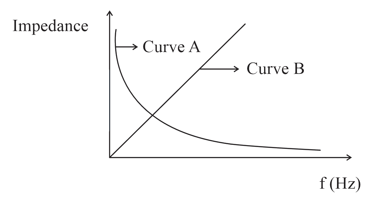
As per the given graph, choose the correct representation for curve and curve
{Where Reactance of pure capacitive circuit connected with A.C. source
Reactance of pure inductive circuit connected with A.C. source
Impedance of pure resistive circuit connected with A.C. source
Impedance of the series circuit }JEE Main/MCQ/Medium/AC Circuits/With diagram - 78Given below are two statements:
Statement I: Maximum power is dissipated in a circuit containing an inductor, a capacitor and a resistor connected in series with an source, when resonance occurs.
Statement II: Maximum power is dissipated in a circuit containing pure resistor due to zero phase difference between current and voltage.
In the light of the above statements, choose the correct answer from the options given below:JEE Main/MCQ/Medium/AC Circuits - 79An oscillating circuit consists of a inductor and a capacitor. If the maximum charge to the capacitor is . The maximum current in the circuit will be _______mA.JEE Main/Numerical/Medium/AC Circuits
- 80A series LCR circuit is connected to an ac source of . The circuit contain a resistance and an inductor of inductive reactance . The capacitance of the capacitor needed to maximize the average rate at which energy is supplied will be ______ .JEE Main/Numerical/Medium/AC Circuits
- 81An inductor of , a capacitor of and resistance of are connected in series with a ac source. If the current is in phase with the emf, the amplitude of current of the circuit is . The value of is-JEE Main/Numerical/Medium/AC Circuits
- 82In the given circuit, value of current through the resistor is :
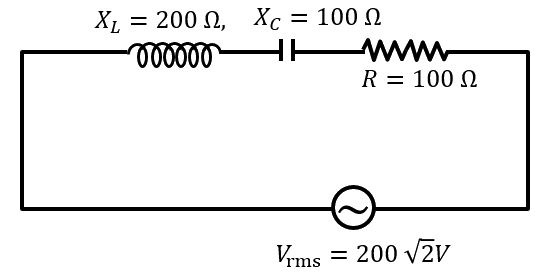 JEE Main/MCQ/Medium/AC Circuits/With diagram
- 83An inductor of inductance is connected in series with a resistance, a variable capacitor and an AC source of frequency . The value of capacitance for which maximum current is drawn into the circuit is , where the value of is ______.
(Take )JEE Main/Numerical/Medium/AC Circuits - 84For the given figures, choose the correct options:
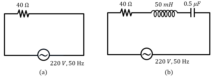 JEE Main/MCQ/Medium/AC Circuits/With diagram
- 85An LCR series circuit of capacitance and resistance of , is connected to an A.C. source of frequency . For maximum value of amplitude of current in circuit, the value of inductance is ____.JEE Main/Numerical/Medium/AC Circuits
- 86In an LC oscillator, if values of inductance and capacitance become twice and eight times, respectively, then the resonant frequency of oscillator becomes times its initial resonant frequency . The value of is:JEE Main/MCQ/Medium/AC Circuits
- 87A capacitor of capacitance is charged completely using a de supply of . It is now connected to an inductor of inductance to form an LC circuit. The maximum current in LC circuit will be _____ .JEE Main/Numerical/Medium/AC Circuits
- 88A circuit element when connected to an AC supply of peak voltage gives a peak current of which is in phase with the voltage. A second element when connected to the same AC supply also gives the same value of peak current which lags behind the voltage by . If and are connected in series to the same supply, what will be the rms value of the current in ampere?JEE Main/MCQ/Medium/AC Circuits
- 89A coil of inductance and resistance is connected to a battery of . Determine approximately :
(a) The time elapsed before the current acquires half of its steady-state value
(b) The energy stored in the magnetic field associated with the coil at an instant after the circuit is switched on. (Given , )JEE Main/MCQ/Medium/AC Circuits - 90The frequencies at which the current amplitude in an LCR series circuit becomes times its maximum value, are and . The value of resistance in the circuit is . The self inductance in the circuit is _____ .JEE Main/Numerical/Medium/AC Circuits
- 91A series LCR circuit has and and it is connected to ac voltage of amplitude . At frequency lower than resonant frequency, the amplitude of current will be approximatelyJEE Main/MCQ/Medium/AC Circuits
- 92To light, a lamp is connected, in series with a capacitor of capacitance , with source. The value of will be _____ .JEE Main/Numerical/Medium/AC Circuits
- 93The effective current in the given circuit at very high frequencies will be _____ .
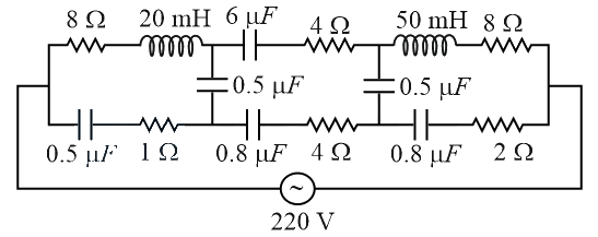 JEE Main/Numerical/Medium/AC Circuits/With diagram
- 94When you walk through a metal detector carrying a metal object in your pocket, it raises an alarm. This phenomenon works onJEE Main/MCQ/Medium/AC Circuits
- 95The RMS value of conduction current in a parallel plate capacitor is . The capacity of this capacitor, if it is connected to AC supply with an angular frequency of , will beJEE Main/MCQ/Medium/AC Circuits
- 96To increase the resonant frequency in series LCR circuit,JEE Main/MCQ/Medium/AC Circuits
- 97For a series circuit, vs curve is shown
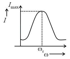
(a) To the left of , the circuit is mainly capacitive.
(b) To the left of , the circuit is mainly inductive.
(c) At , impedance of the circuit is equal to the resistance of the circuit.
(d) At , impedance of the circuit is .
Choose the most appropriate answer from the options given below.JEE Main/MCQ/Medium/AC Circuits/With diagram - 98In the given circuit, the magnitude of and are twice that of . Given that , the inductance of the coil is . The value of is _____ .
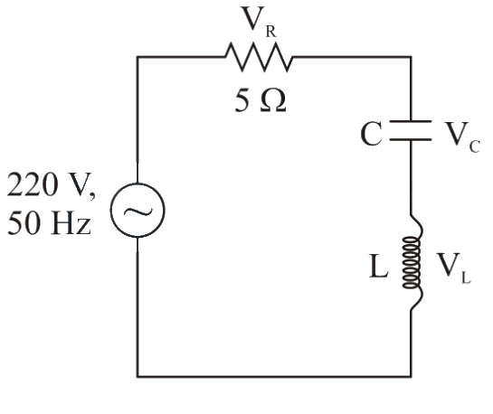 JEE Main/Numerical/Medium/AC Circuits/With diagram
- 99An AC source is connected to an inductance of , a capacitance of and a resistance of as shown in figure. The time in which the resistance having a thermal capacity will get heated by is _____ .
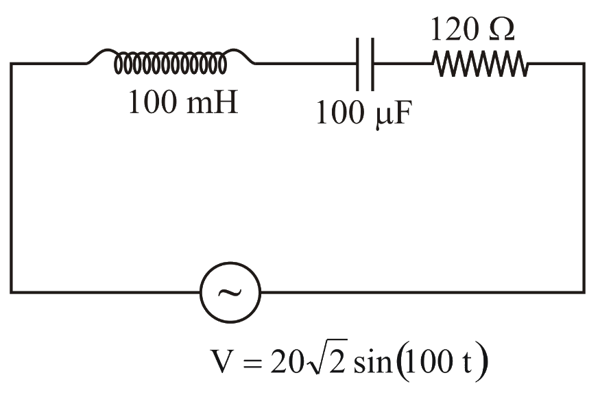 JEE Main/Numerical/Medium/AC Circuits/With diagram
- 100A source is connected in the circuit (as shown in figure). The current through the resistance , at resonance in the circuit, will be _____.
 JEE Main/Numerical/Medium/AC Circuits/With diagram
- 101In a series LCR circuit, the inductance, capacitance and resistance are , and respectively. They are connected to an source of voltage and frequency of . The approximate value of current in the circuit will be _____ .
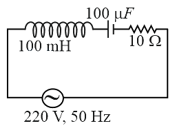 JEE Main/Numerical/Medium/AC Circuits/With diagram
- 102If wattless current flows in the circuit, then the circuit is :JEE Main/MCQ/Medium/AC Circuits
- 103In an ac circuit, an inductor, a capacitor and a resistor are connected in series with Impedance of this circuit is :JEE Main/MCQ/Medium/AC Circuits
- 104An inductor coil stores of magnetic field energy and dissipates energy at the rate of when a current of is passed through it. If this coil is joined across an ideal battery, find the time constant of the circuit (in ).JEE Main/MCQ/Medium/AC Circuits
- 105A series LCR circuit driven by at a frequency of contains a resistance , an inductor of inductive reactance and an unknown capacitor. The value of capacitance to maximise the average power should be:
JEE Main/MCQ/Medium/AC Circuits - 106A resistance, a capacitor and an inductor are connected in series across a supply at variable frequency. Calculate the value of inductance of inductor at which resonance will occur. Given that the resonant frequency is .JEE Main/MCQ/Medium/AC Circuits
- 107A inductor and a resistor are connected in series to a AC source. The approximate current in the circuit and the phase angle between current and source voltage are respectively.
[Take as JEE Main/MCQ/Medium/AC Circuits - 108Two circuits are shown in figure and . At a frequency of _______ the average power dissipated in one cycle will be the same in both the circuits.
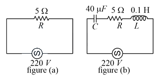 JEE Main/Numerical/Medium/AC Circuits/With diagram
- 109An inductor of is connected to a battery through a resistor of and a switch. After a long time, when maximum current is set up in the circuit, the current is switched off. The current in the circuit after is . Then is equal to ______ . (Take )JEE Main/Numerical/Medium/AC Circuits
- 110Match List-I with List-II. List - I List - II (a) (i) Current is in phase with emf (b) (ii) Current lags behind the applied emf (c) (iii) Maximum current occurs (d) Resonant frequency (iv) Current leads the emf Choose the correct answer from the options given below.JEE Main/MCQ/Medium/AC Circuits
- 111A series LCR circuit of and is connected across an supply of having variable frequency. The power dissipated at resonance condition is ________JEE Main/Numerical/Medium/AC Circuits
- 112For a series circuit with and connected across supply, the phase angle between
current and supplied voltage and the nature of the circuit is:JEE Main/MCQ/Medium/AC Circuits - 113In an series circuit, an inductor and a resistor are connected to an source of angular frequency The value of capacitance for which the current leads the voltage by is . Then the value of isJEE Main/Numerical/Medium/AC Circuits
- 114The time taken for the magnetic energy to reach of its maximum value, when a solenoid of resistance , inductance is connected to a battery, is :JEE Main/MCQ/Medium/AC Circuits
- 115In a scries resonance circuit, if we change the resistance only, from a lower to higher value :JEE Main/MCQ/Medium/AC Circuits
- 116A sinusoidal voltage of peak value is applied to a series circuit, in which and . The value of power dissipated at resonant condition is . The value of to the nearest integer is _______.JEE Main/Numerical/Medium/AC Circuits
- 117An circuit as shown in the figure is driven by a source generating a square wave. The output wave pattern monitored by would look close to :
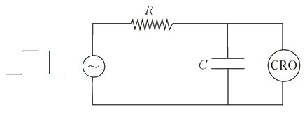 JEE Main/MCQ/Medium/AC Circuits/With diagram
- 118In a series LCR resonant circuit, the quality factor is measured as . If the inductance is increased by two fold and resistance is decreased by two fold, then the quality factor after this change will be _______JEE Main/Numerical/Medium/AC Circuits
- 119An circuit contains resistance of and a supply of at angular frequency. If only capacitance is removed from the circuit, current lags behind the voltage by . If on the other hand, the only the inductor is removed the current leads by with the applied voltage. The current flowing in the circuit will be:JEE Main/MCQ/Medium/AC Circuits
- 120A transmitting station releases waves of wavelength . A capacitor of is used in the resonant circuit. The self-inductance of coil necessary for resonance is . find JEE Main/Numerical/Medium/AC Circuits
- 121The angular frequency of alternating current in a L-C-R circuit is . The components connected are shown in the figure. Find the value of inductance of the coil and capacity of condenser.
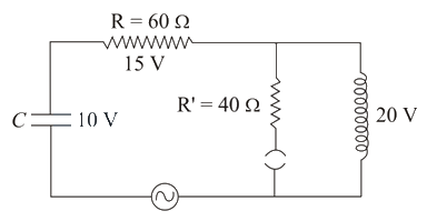 JEE Main/MCQ/Medium/AC Circuits/With diagram
- 122The current at time and respectively for the given circuit is :
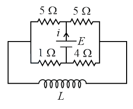 JEE Main/MCQ/Medium/AC Circuits/With diagram
- 123A series LCR circuit is designed to resonate at an angular frequency The circuit draws power from source at resonance. The value of resistance in the circuit is ________ JEE Main/Numerical/Medium/AC Circuits
- 124In a series circuit, power of is dissipated from a source of . The power factor of the circuit is . In order to bring the power factor to unity, a capacitor of value is added in series to the and . Taking the value of as , then value of isJEE Main/Numerical/Medium/AC Circuits
- 125A series circuit is connected to a battery of emf . If the circuit is switched on at , then the time at which the energy stored in the inductor reaches times of its maximum value, is :JEE Main/MCQ/Medium/AC Circuits
- 126A source is connected to a resistance of an inductance of and a capacitance of all in series. The time in which the resistance (heat capacity ) will get heated by (assume no loss of heat to the surroundings) is close to :JEE Main/MCQ/Medium/AC Circuits
- 127Two identical capacitors and charged to the same potential are connected in two different circuits as shown below at time If the charge on capacitors and at time is and respectively, then (Here is the base of natural logarithm)
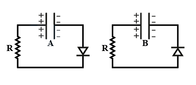 JEE Main/MCQ/Medium/AC Circuits/With diagram
- 128In circuit the inductance and capacitance If a voltage is applied to the circuit, the current in the circuit is given as:JEE Main/MCQ/Medium/AC Circuits
- 129
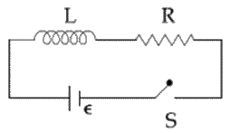
As shown in the figure, a battery of emf is connected to an inductor and resistance in series. The switch is closed at The total charge that flows from the battery, between and ( is the time constant of the circuit) is:JEE Main/MCQ/Medium/AC Circuits/With diagram - 130An emf of is applied at time to a circuit containing in series inductor and resistor. The ratio of the currents at time and at is close to: (Take )JEE Main/MCQ/Medium/AC Circuits
- 131A circuit behaves like a clamped harmonic oscillator. Comparing it with a physical spring-mass damped oscillator having damping constant the correct equivalence would be:JEE Main/MCQ/Medium/AC Circuits
- 132Consider the LR circuit shown in the figure. If the switch S is closed at then the amount of charge that passes through the battery between and is:
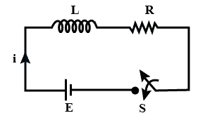 JEE Main/MCQ/Medium/AC Circuits/With diagram
- 133A circuit connected to an ac source of emf with in seconds, gives a phase difference of between the emf and current . Which of the following circuits will exhibit this?JEE Main/MCQ/Medium/AC Circuits
- 134A inductor coil is connected to a resistance in series as shown in figure. The time at which rate of dissipation of energy (Joule's heat) across resistance is equal to the rate at which magnetic energy is stored in the inductor, is:
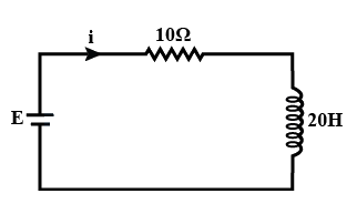 JEE Main/MCQ/Medium/AC Circuits/With diagram
- 135In the figure shown, a circuit contains two identical resistors with resistance and an inductance with An ideal battery of is connected in the circuit. What will be the current through the battery long after the switch is closed?
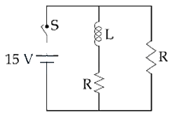 JEE Main/MCQ/Medium/AC Circuits/With diagram
- 136In the circuit shown,
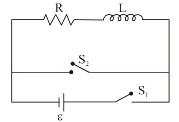
the switch is closed at time and the switch is kept open. At some later time , the switch is opened and is closed. the behaviour of the current I as a function of time ' ' is given by:JEE Main/MCQ/Medium/AC Circuits/With diagram - 137An ideal capacitor of capacitance is charged to a potential difference of . The charging battery is then disconnected. The capacitor is then connected to an ideal inductor of self inductance . The current at a time when the potential difference across the capacitor is is:JEE Main/MCQ/Medium/AC Circuits
- 138A sinusoidal voltage of peak value and angular frequency is applied to a series circuit. Given that and . The total impedance and phase difference between the voltage across the source and the current will respectively be-JEE Main/MCQ/Medium/AC Circuits
- 139A series circuit is connected to a voltage source with . After a very large time, current behaves as :JEE Main/MCQ/Medium/AC Circuits
- 140An arc lamp requires a direct current of 10 A at 80 V to function. If it is connected to a 220 V (rms), 50 Hz AC supply, the series inductor needed for it to work is close to:JEE Main/MCQ/Medium/AC Circuits
- 141For the LCR circuit, shown here, the current is observed to lead the applied voltage. An additional capacitor , when joined with the capacitor C present in the circuit, makes the power factor of the circuit unity. The capacitor , must have been connected in:
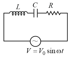 JEE Main/MCQ/Medium/AC Circuits/With diagram
- 142An inductor and a resistor are connected in series to a battery of E.M.F. in a circuit shown below. The key has been kept closed for a long time. Then at , is opened and key is closed simultaneously. At , the current in the circuit will be :
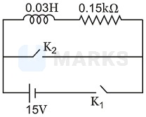 JEE Main/MCQ/Medium/AC Circuits/With diagram
- 143An LCR circuit is equivalent to a damped pendulum. In an LCR circuit the capacitor is charged to and then connected to the L and R as shown below:
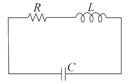
If a student plots graphs of the square of maximum charge on the capacitor with time (t) for two different values and of L then which of the following represents this graph correctly? (plots are schematic and not drawn to scale)JEE Main/MCQ/Medium/AC Circuits/With diagram - 144When the rms voltages and are measured respectively across the inductor the capacitor and the resistor in a series circuit connected to an source, it is found that the ratio If the rms voltage of the source is then is close to :JEE Main/MCQ/Medium/AC Circuits
- 145In the circuit shown here, the point '' is kept connected to point '' till the current flowing through the circuit becomes constant. Afterward, suddenly, point '' is disconnected from point '' and connected to point '' at time . Ratio of the voltage across resistance and the inductor at will be equal to :
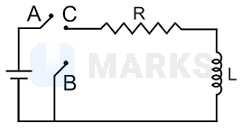 JEE Main/MCQ/Medium/AC Circuits/With diagram
- 146When resonance is produced in a series LCR circuit, then which of the following is not correct?JEE Main/MCQ/Medium/AC Circuits
- 147In a series circuit, Farad, Henry and , when a constant D.C. voltage is applied to the circuit, the capacitor acquires a charge C. The D.C. source is replaced by a sinusoidal voltage source in which the peak voltage is equal to the constant D.C. voltage E. At resonance the peak value of the charge acquired by the capacitor will be :JEE Main/MCQ/Medium/AC Circuits
- 148An LCR circuit as shown in the figure is connected to a voltage source whose frequency can be varied.
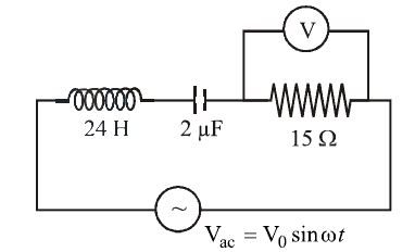
The frequency, at which the voltage across the resistor is maximum, is :JEE Main/MCQ/Medium/AC Circuits/With diagram - 149In the circuit shown here, the voltage across and are respectively and . The voltage of the ac source is :
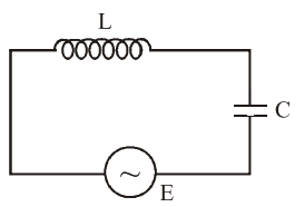 JEE Main/MCQ/Medium/AC Circuits/With diagram
- 150The amplitude of a damped oscillator decreases to 0.9 times its original magnitude in 5s. In another 10s it will decrease to times its original magnitude, where equals :JEE Main/MCQ/Medium/AC Circuits
- 151A resistance and a capacitance are connected in series to a battery of negligible internal resistance through a key. The key is closed at 0 . If after sec the voltage across the capacitance was seven times the voltage across , the value of isJEE Main/MCQ/Medium/AC Circuits
- 152In an circuit shown in the following figure, what will be the readings of the voltmeter across the resistor and ammeter if an a.c. source of and is connected to it as shown?
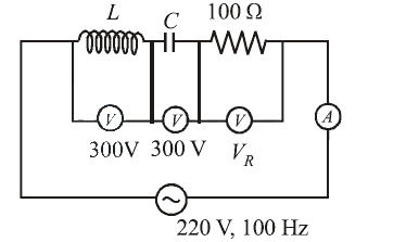 JEE Main/MCQ/Medium/AC Circuits/With diagram
- 153A fully charged capacitor with initial charge is connected to a coil of self inductance at . The time at which the energy is stored equally between the electric and the magnetic field is :JEE Main/MCQ/Medium/AC Circuits
- 154In a series LCR circuit and the voltage and the frequency of the main supply is and respectively. On taking out the capacitance from the circuit the current lags behind the voltage by . On taking out the inductor from the circuit the current leads the voltage by . The power dissipated in the LCR circuit isJEE Main/MCQ/Medium/AC Circuits
- 155An inductor , a resistor and a battery are initially connected in series as shown in the figure. After a long time the battery is disconnected after short circuiting the points and . The current in the circuit after the circuit is
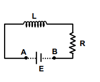 JEE Main/MCQ/Medium/AC Circuits/With diagram
- 156In a series resonant LCR circuit, the voltage across is 100 volts and with . The resonant frequency is . At resonance the voltage across isJEE Main/MCQ/Medium/AC Circuits
- 157The phase difference between the alternating current and emf is . Which of the following cannot be the constituent of the circuit?JEE Main/MCQ/Medium/AC Circuits
- 158In a LCR circuit capacitance is changed from to . For the resonant frequency to remain unchanged, the inductance should be changed from toJEE Main/MCQ/Medium/AC Circuits
- 159In an LCR series a.c. circuit, the voltage across each of the components, and is . The voltage across the LC combination will beJEE Main/MCQ/Medium/AC Circuits
- 160In an oscillating LC circuit the maximum charge on the capacitor is Q. The charge on the capacitor when the energy is stored equally between the electric and magnetic field isJEE Main/MCQ/Medium/AC Circuits
- 161For the series circuit connected with a.c source as shown in the figure, the power factor is . The value of is .
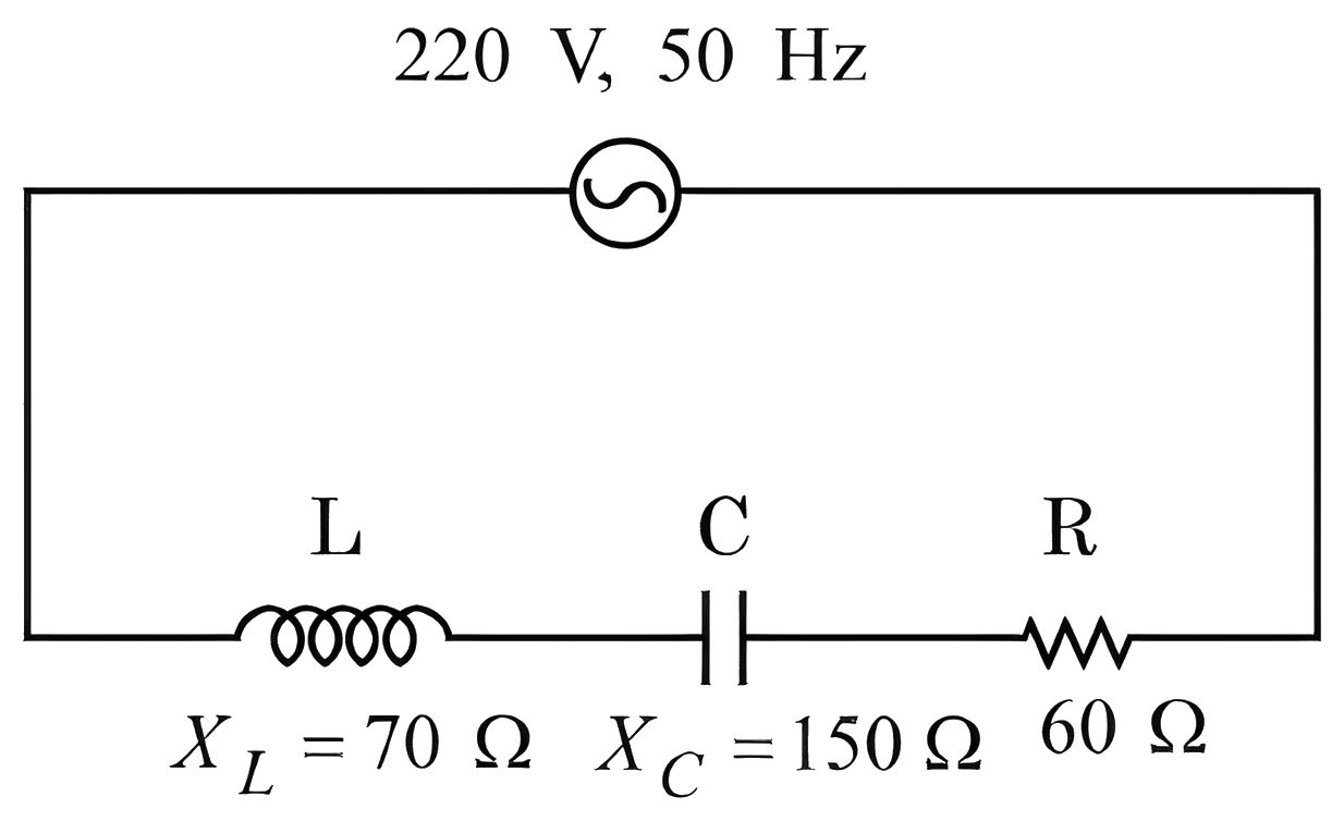 JEE Main/MCQ/Medium/Quality and Power Factor/With diagram
- 162A series circuit connected with an ac source has a power factor of . If the source of emf is changed to , the new power factor of the circuit will be :JEE Main/MCQ/Medium/Quality and Power Factor
- 163A series LCR circuit with and , is connected across an AC source of supply. The power factor of the circuit would be ____.JEE Main/Numerical/Medium/Quality and Power Factor
- 164In a series circuit with , power factor is . If a capacitor of capacitance with is added to the circuit the power factor becomes . The ratio of to will be :JEE Main/MCQ/Medium/Quality and Power Factor
- 165A series LCR circuit is connected to an AC source of , . The circuit contains a resistance , an inductor of inductive reactance , and a capacitor of capacitive reactance . The power factor of circuit is . The value of is:JEE Main/Numerical/Medium/Quality and Power Factor
- 166In a series LCR circuit, the inductive reactance is and the capacitive reactance is . The resistance in the circuit is . The power factor of the circuit is :JEE Main/MCQ/Medium/Quality and Power Factor
- 167In an circuit, the instantaneous e.m.f. and current are given by, . In one cycle of , the average power consumed by the circuit (in watt) and the watt-less current (in ampere) are, respectively:JEE Main/MCQ/Medium/Quality and Power Factor
- 168A series circuit is connected to an ac source of frequency and the inductive reactance is equal to . A capacitance of capacitive reactance equal to is added in series with and . The ratio of the new power factor to the old one is :JEE Main/MCQ/Medium/Quality and Power Factor
- 169A circuit has a resistance of and an impedance of . The power factor of the circuit will beJEE Main/MCQ/Medium/Quality and Power Factor
- 170The power factor of an circuit having resistance and inductance connected in series and an angular velocity isJEE Main/MCQ/Medium/Quality and Power Factor
- 171A transformer has an efficiency of and works at and If the secondary voltage is then the current in the secondary coil is:JEE Main/MCQ/Medium/Transformers
- 172A power transmission line feeds input power at to a step down transformer with its primary winding having . The output power is delivered at by the transformer. The current in the primary of the transformer is and its efficiency is . The winding of transformer is made of copper. The output current of transformer is ____.JEE Main/Numerical/Medium/Transformers
- 173Primary coil of a transformer is connected to . Primary and secondary turns of the transforms are and respectively. Secondary coil of transformer is connected to two series resistances as shown in figure. The output voltage is :
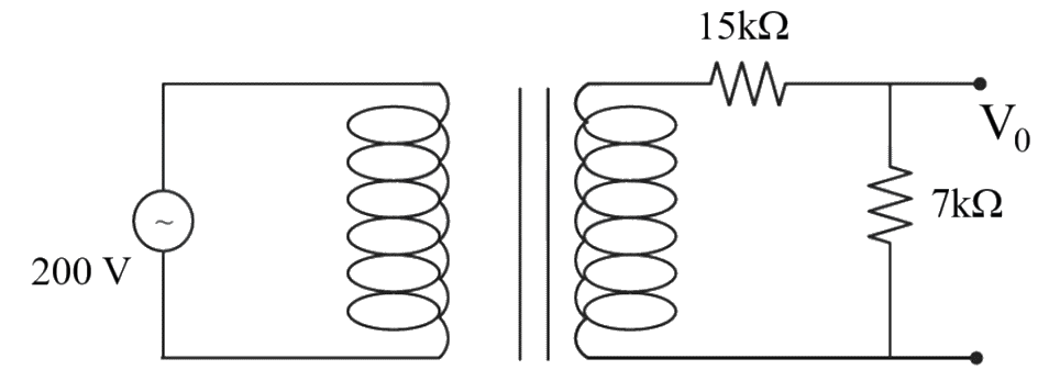 JEE Main/MCQ/Medium/Transformers/With diagram
- 174The primary side of a transformer is connected to supply. The turn ratio of primary to secondary winding is . Load resistance connected to the secondary side is . The power consumed in it is:JEE Main/MCQ/Medium/Transformers
- 175An ideal transformer with purely resistive load operates at on the primary side. It supplies electrical energy to a number of nearby houses at The average rate of energy consumption in the houses served by the transformer is The value of resistive load required in the secondary circuit will be_________m\Omega .JEE Main/Numerical/Medium/Transformers
- 176Match the List-I with List-II. List I List II A AC generator I Presence of both L and C B Transformer II Electromagnetic Induction C Resonance phenomenon to occur III Quality factor D Sharpness of resonance IV Mutual Inductance Choose the correct answer from the options given below:JEE Main/MCQ/Medium/Transformers
- 177A transformer operating at primary voltage and secondary voltage serves a load of . Assuming the transformer to be ideal with purely resistive load and working on unity power factor, the loads in the primary and secondary circuit would beJEE Main/MCQ/Medium/Transformers
- 178Match List - I with List - II. List-I List-II (A) AC generator (I) Detects the presence of current in the circuit (B) Galvanometer (II) Converts mechanical energy into electrical energy (C) Transformer (III) Works on the principle of resonance in AC circuit (D) Metal detector (IV) Changes an alternating voltage for smaller or greater valueJEE Main/MCQ/Medium/Transformers
- 179For the given circuit, comment on the type of transformer used :
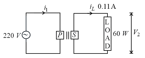 JEE Main/MCQ/Medium/Transformers/With diagram
- 180A common transistor radio set requires for its operation. The source is constructed by using a transformer and a rectifier circuit, which are operated at on standard domestic supply. The number of turns of secondary coil are then the number of turns of primary areJEE Main/Numerical/Medium/Transformers
- 181Magnetic materials used for making permanent magnets and magnets in a transformer have different properties of the following, which property best matches for the type of magnet required?JEE Main/MCQ/Medium/Transformers
- 182A transformer consisting of turns in the primary and turns in the secondary gives output power of . If the current in the secondary coil is , then the input voltage and current in the primary coil are:JEE Main/MCQ/Medium/Transformers
- 183A power transmission line feeds input power at to a step down transformer with its primary windings having turns. The output power is delivered at by the transformer. If the current in the primary of the transformer is and its efficiency is , the output current would be:JEE Main/MCQ/Medium/Transformers
- 184A power transmission line feeds input power at to a step-down transformer with its primary windings having turns giving the output power at . If the current in the primary coil of the transformer is and its efficiency is , the output current would be:JEE Main/MCQ/Medium/Transformers
- 185Alternating current can not be measured by D.C. ammeter becauseJEE Main/MCQ/Medium/Transformers
- 186The core of any transformer is laminated so as toJEE Main/MCQ/Medium/Transformers
- 187In a transformer, number of turns in the primary coil are 140 and that in the secondary coil are 280. If current in primary coil is , then that in the secondary coil isJEE Main/MCQ/Medium/Transformers
- 188An inductor of self inductance 1 H connected in series with a resistor of and an ac supply of volt, 50 Hz. Maximum current flowing in the circuit is ________ A.JEE Main/Numerical/Medium/Parallel AC Circuits
- 189Three identical resistors with resistance and two identical inductors with sell inductance are connected to an ideal battery with emf of as shown in figure. The current through the battery long after the switch has been closed will be________.
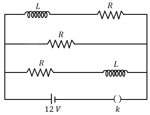 JEE Main/Numerical/Medium/Parallel AC Circuits/With diagram
- 190The figure shows a circuit that contains four identical resistors with resistance two identical inductors with inductance and an ideal battery with E.M.F. The current just after the switch is closed will be:
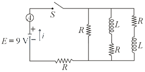 JEE Main/MCQ/Medium/Parallel AC Circuits/With diagram
NEET question paper PDF
This chapter includes NEET questions. Open a year to read the full paper, or download the PDF.
Opening paper…
JEE Main question paper PDF
This chapter includes JEE Main questions. Open a shift to read the paper, or download the PDF.
Opening paper…
Other Physics chapters
Current Electricity 380Electrostatics 311Kinematics 308Ray Optics 295Rotational Motion 280Magnetic Effects & Magnetism 276Atoms & Nuclei 239Gravitation 223Laws of Motion 210Semiconductors 209Dual Nature of Matter 200Oscillations 194Fluid Mechanics 192Wave Optics 191Thermodynamics 190Work Energy Power 183Capacitors 180Kinetic Theory 168Electromagnetic Waves 165Electromagnetic Induction 153Units & Dimensions 149Waves 142Center of Mass, Momentum & Collision 130Thermal Properties of Matter 126Mathematics in Physics 121Mechanical Properties of Solids 118Experimental Physics 70Magnetic Properties of Matter 57Modern Physics 5
Stuck on a Alternating Current question from your book?
Snap it and get a whiteboard video that solves it step by step. Your first video needs no login.