Physics · JEE Main, NEET
Current Electricity
380 practice questions with a worked solution for each. Tap an option to see instantly if you are right.
282MCQ98Numerical162With diagram
- 1In the given electrical circuit network between terminals and , resistors are , , , and . Determine the equivalent resistance .JEE Main/MCQ/Medium/With diagram
- 2In the given meter bridge setup, null point is found at distance from end . If the known standard resistor is , the value of the unknown resistance in the left gap is:NEET/MCQ/Medium/With diagram
- 3A wire of resistance is stretched to double its original length keeping volume constant. Its new resistance is:NEET/MCQ/Medium
- 4In an experiment to determine the resistance of a given wire using Ohm's law, the voltmeter and ammeter readings are noted as and , respectively. The least counts of voltmeter and ammeter are and , respectively. The estimated error in the resistance measurement is _______ .JEE Main/MCQ/Medium/Electric Current and Drift of Electrons
- 5Which one of the following is not a measurable quantity?JEE Main/MCQ/Medium/Electric Current and Drift of Electrons
- 6A cylindrical conductor of length 2 m and area of cross-section carries an electric current of 1.6 A when its ends are connected to a 2 V battery. Mobility of electrons in the conductor is . The value of is :
(electron concentration and electron charge JEE Main/Numerical/Medium/Electric Current and Drift of Electrons - 7Current passing through a wire as function of time is given as . The charge that will flow through the wire from to is :JEE Main/MCQ/Medium/Electric Current and Drift of Electrons
- 8The current in a conductor is expressed as , where is in Ampere and is in second. The amount of electric charge that flows through a section of the conductor during to is ____________ JEE Main/Numerical/Medium/Electric Current and Drift of Electrons
- 9The electric current through a wire varies with time as , where and . The amount of electric charge crossed through a section of the wire in is:JEE Main/MCQ/Medium/Electric Current and Drift of Electrons
- 10The current flowing through a conductor connected across a source is and at and respectively. The current flowing through the conductor at will be _____ .JEE Main/Numerical/Medium/Electric Current and Drift of Electrons
- 11In a metallic conductor, under the effect of applied electric field, the free electrons of the conductorJEE Main/MCQ/Medium/Electric Current and Drift of Electrons
- 12The number density of free electrons in copper is nearly . A copper wire has its area of cross-section and is carrying a current of . The drift speed of the electrons is _____.JEE Main/Numerical/Medium/Electric Current and Drift of Electrons
- 13A current of flows through a wire of cross-sectional area . The number of free electrons in a cubic meter are . The drift velocity of the electrons is _____
(given, charge on electron ).JEE Main/Numerical/Medium/Electric Current and Drift of Electrons - 14The drift velocity of electrons for a conductor connected in an electrical circuit is . The conductor is now replaced by another conductor with same material and same length but double the area of cross-section. The applied voltage remains same. The new drift velocity of electrons will beJEE Main/MCQ/Medium/Electric Current and Drift of Electrons
- 15The charge flowing in a conductor changes with time as , where and are constants. Minimum value of current is:JEE Main/MCQ/Medium/Electric Current and Drift of Electrons
- 16A. The drift velocity of electrons decreases with the increase in the temperature of conductor.
B. The drift velocity is inversely proportional to the area of cross-section of given conductor.
C. The drift velocity does not depend on the applied potential difference to the conductor.
D. The drift velocity of electron is inversely proportional to the length of the conductor.
E. The drift velocity increases with the increase in the temperature of conductor.
Choose the correct answer from the options given below:JEE Main/MCQ/Medium/Electric Current and Drift of Electrons - 17For the network shown below, the value of is _____ .
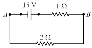 JEE Main/Numerical/Medium/Electric Current and Drift of Electrons/With diagram
- 18The current density in a cylindrical wire of radius is . The current through the outer portion of the wire between radial distances and is ; where isJEE Main/Numerical/Medium/Electric Current and Drift of Electrons
- 19The current density in a cylindrical wire of radius is . The current through the outer portion of the wire between radial distances and is _____ .JEE Main/Numerical/Medium/Electric Current and Drift of Electrons
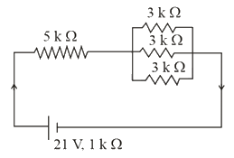
- 20The total current supplied to the circuit as shown in figure by the battery is _____ .
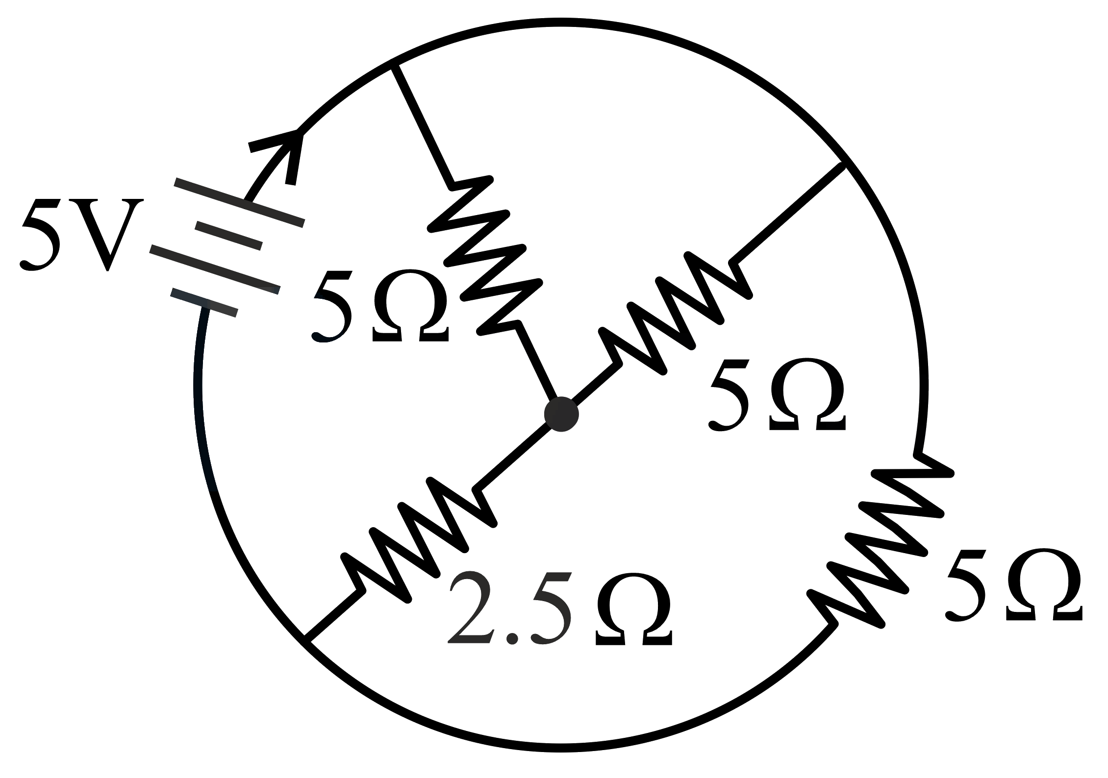 JEE Main/Numerical/Medium/Electric Current and Drift of Electrons/With diagram
- 21For the circuit shown, the value of current at time will be ______ .
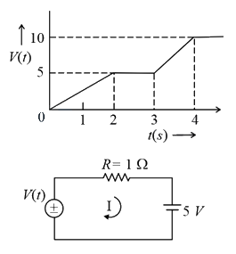
[Voltage distribution is shown by Fig. and the circuit is shown in Fig. ]JEE Main/Numerical/Medium/Electric Current and Drift of Electrons/With diagram - 22A current of is passing through a non-linear magnesium wire of cross-section . At every point the direction of current density is at an angle of with the unit vector of area of cross-section.
The magnitude of electric field at every point of the conductor is: (resistivity of magnesium )JEE Main/MCQ/Medium/Electric Current and Drift of Electrons - 23The circuit shown in the figure consists of a charged capacitor of capacity and a charge of At time when the key is closed, the value of current flowing through the resistor is The value of to the nearest integer is
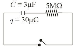 JEE Main/Numerical/Medium/Electric Current and Drift of Electrons/With diagram
- 24In the experiment of Ohm's law, a potential difference of is applied across the end of a conductor of length and diameter of The measured current in the conductor is The maximum permissible percentage error in the resistivity of the conductor is :-JEE Main/MCQ/Medium/Electric Current and Drift of Electrons
- 25Seawater at a frequency , has permittivity and resistivity . Imagine a parallel plate capacitor is immersed in seawater and is driven by an alternating voltage source . Then the conduction current density becomes times the displacement current density after time The value of is _______
(Given JEE Main/Numerical/Medium/Electric Current and Drift of Electrons - 26A current of exists in a wire of cross-sectional area of with a drift velocity of The number of free electrons in each cubic meter of the wire isJEE Main/MCQ/Medium/Electric Current and Drift of Electrons
- 27In the figure given, the electric current flowing through the resistor is .
The value of to the nearest integer is ________.JEE Main/Numerical/Medium/Electric Current and Drift of Electrons/With diagram - 28A cylindrical wire of radius and conductivity is subjected to an electric field of The expected value of current in the wire will be The value of is _________.JEE Main/Numerical/Medium/Electric Current and Drift of Electrons
- 29A current through a wire depends on time as , where and . Find the charge crossed through a section of the wire in JEE Main/MCQ/Medium/Electric Current and Drift of Electrons
- 30A current of passes through a copper conductor (resistivity ) of radius of cross-section . Find the mobility of the charges if their drift velocity is .JEE Main/MCQ/Medium/Electric Current and Drift of Electrons
- 31In a conductor, if the number of conduction electrons per unit volume is and mean free time is (femto second), it’s approximate resistivity is: JEE Main/MCQ/Medium/Electric Current and Drift of Electrons
- 32The charge on a capacitor plate in a circuit, as a function of time, is shown in the figure:
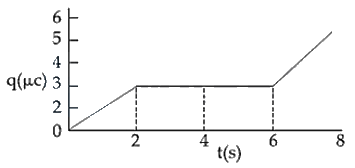
What is the value of current at JEE Main/MCQ/Medium/Electric Current and Drift of Electrons/With diagram - 33Mobility of electrons in a semiconductor is defined as the ratio of their drift velocity to the applied electric field. If, for an -type semiconductor, the density of electrons is and their mobility is , then the resistivity of the semiconductor (since it is an -type semiconductor contribution of holes is ignored) is close to:JEE Main/MCQ/Medium/Electric Current and Drift of Electrons
- 34Drift speed of electrons, when current flows in a copper wire of cross section is If the electron density in copper is the value of in is close to (Take charge of an electron to be )JEE Main/MCQ/Medium/Electric Current and Drift of Electrons
- 35Suppose the drift velocity in a material varied with the applied electric field E as . Then graph for a wire made of such a material is best given by:JEE Main/MCQ/Medium/Electric Current and Drift of Electrons
- 36When potential difference is applied across a wire of length , the drift speed of electrons is . If the electron density in the wire is , the resistivity of the material is close to:JEE Main/MCQ/Medium/Electric Current and Drift of Electrons
- 37A generator has armature resistance of and develops an induced emf of when driven at its rated speed. Its terminal voltage when a current of is being drawn isJEE Main/MCQ/Medium/Electric Current and Drift of Electrons
- 38This question has Statement 1 and Statement 2. Of the four choices given after the Statements, choose the one that best describes the two Statements.
Statement 1: The possibility of an electric bulb fusing is higher at the time of switching .
Statement 2: Resistance of an electric bulb when it is not lit up is much smaller than when it is lit up.JEE Main/MCQ/Medium/Electric Current and Drift of Electrons - 39Paragraph:
Consider a block of conducting material of resistivity ' ' shown in the figure. Current 'l' enters at 'A' and leaves from ' '. We apply superposition principle to find voltage ' ' developed between ' ' and ' '. The calculation is done in the following steps:
(i) Take current 'l' entering from 'A' and assume it to spread over a hemispherical surface in the block.
(ii) Calculate field at distance ' ' from by using Ohm's law , where is the current per unit area at ' '.
(iii) From the ' ' dependence of , obtain the potential at .
(iv) Repeat (i), (ii) and (iii) for current 'l' leaving ' ' and superpose results for ' ' and ' '.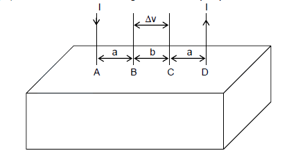
Question:
For current entering at , the electric field at a distance ' ' from isJEE Main/MCQ/Medium/Electric Current and Drift of Electrons/With diagram - 40Paragraph:
Consider a block of conducting material of resistivity ' ' shown in the figure. Current 'l' enters at 'A' and leaves from ' '. We apply superposition principle to find voltage ' ' developed between ' ' and ' '. The calculation is done in the following steps:
(i) Take current 'l' entering from 'A' and assume it to spread over a hemispherical surface in the block.
(ii) Calculate field at distance ' ' from by using Ohm's law , where is the current per unit area at ' '.
(iii) From the ' ' dependence of , obtain the potential at .
(iv) Repeat (i), (ii) and (iii) for current 'l' leaving ' ' and superpose results for ' ' and ' '.
Question:
measured between and isJEE Main/MCQ/Medium/Electric Current and Drift of Electrons/With diagram - 41A thermocouple is made from two metals, Antimony and Bismuth. If one junction of the couple is kept hot and the other is kept cold then, an electric current willJEE Main/MCQ/Medium/Electric Current and Drift of Electrons
- 42An energy source will supply a constant current into the load of its internal resistance isJEE Main/MCQ/Medium/Electric Current and Drift of Electrons
- 43Two sources of equal emf are connected to an external resistance R. The internal resistance of the two sources are and . If the potential difference across the source having internal resistance is zero, thenJEE Main/MCQ/Medium/Electric Current and Drift of Electrons
- 44A wire of length 25 m and cross-sectional area having resistivity of is bent into a complete circle. The resistance between diametrically opposite points will beJEE Main/MCQ/Medium/Resistance and Resistivity
- 45The difference of temperature in a material can convert heat energy into electrical energy. To harvest the heat energy, the material should haveJEE Main/MCQ/Medium/Resistance and Resistivity
- 46A wire of resistance is bent to form an equilateral triangle. Then the equivalent resistance across any two vertices will be _____ ohm.JEE Main/Numerical/Medium/Resistance and Resistivity
- 47Which of the following resistivity ( ) temperature (T) curves is most suitable to be used in wire bound standard resistors?JEE Main/MCQ/Medium/Resistance and Resistivity
- 48Resistance of a wire at and is found to be and respectively. The temperature in Kelvin scale is _________JEE Main/Numerical/Medium/Resistance and Resistivity
- 49A wire of resistance and radius is stretched till its radius became . If new resistance of the stretched wire is , then value of is _______JEE Main/Numerical/Medium/Resistance and Resistivity
- 50Two wires and are made up of the same material and have the same mass. Wire has radius of and wire has radius of . The resistance of wire is . The resistance of wire is _____.JEE Main/Numerical/Medium/Resistance and Resistivity
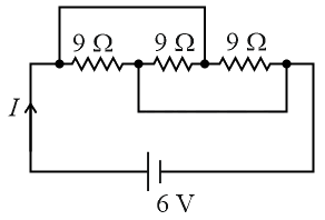
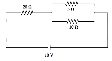
- 51Equivalent resistance of the following network is ________ .
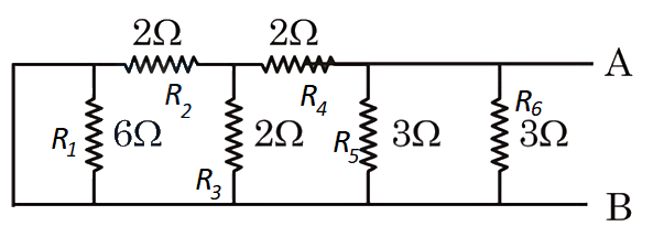 JEE Main/Numerical/Medium/Resistance and Resistivity/With diagram
- 52In the given circuit, the current flowing through the resistance is , while the ammeter reads . The value of is _____.
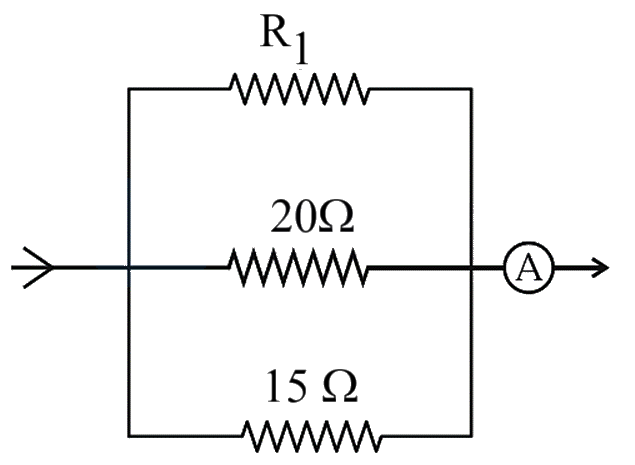 JEE Main/Numerical/Medium/Resistance and Resistivity/With diagram
- 53In the given circuit, the current in resistance is:
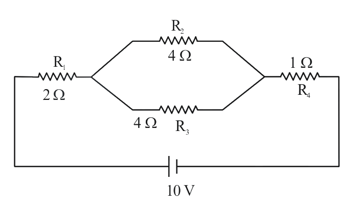 JEE Main/MCQ/Medium/Resistance and Resistivity/With diagram
- 54A wire of resistance and length is cut into equal parts. If these parts are joined parallely, then resultant resistance will be :JEE Main/MCQ/Medium/Resistance and Resistivity
- 55Given below are two statements:
Statement I : The equivalent resistance of resistors in a series combination is smaller than least resistance used in the combination.
Statement II : The resistivity of the material is independent of temperature. In the light of the above statements, choose the correct answer from the options given below:JEE Main/MCQ/Medium/Resistance and Resistivity - 56A wire of resistance is melted and drawn in a wire of one-fourth of its length. The new resistance of the wire will beJEE Main/MCQ/Medium/Resistance and Resistivity
- 57A rectangular parallelopiped is measured as . If its specific resistance is , then the resistance between its two opposite rectangular faces will be _____.
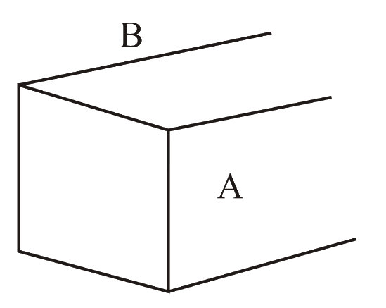 JEE Main/Numerical/Medium/Resistance and Resistivity/With diagram
- 58Given below are two statements : One is labelled as Assertion A and the other is labelled as Reason R.
Assertion A : For measuring the potential difference across a resistance of , the voltmeter with resistance will be preferred over voltmeter with resistance .
Reason R : Voltmeter with higher resistance will draw smaller current than voltmeter with lower resistance.
In the light of the above statements, choose the most appropriate answer from the options given belowJEE Main/MCQ/Medium/Resistance and Resistivity - 59The resistance of a wire is . Its new resistance in ohm, if stretched to times of its original length will be :JEE Main/MCQ/Medium/Resistance and Resistivity
- 60A uniform metallic wire carries a current , when battery is connected across it. The mass of uniform metallic wire is , density is and resistivity is The length of wire is :JEE Main/MCQ/Medium/Resistance and Resistivity
- 61If a copper wire is stretched to increase its length by . The percentage increase in resistance of the wire is _____%.JEE Main/Numerical/Medium/Resistance and Resistivity
- 62A hollow cylindrical conductor has length of , while its inner and outer diameters are and respectively. The resistance of the conductor is .
If the resistivity of the material is . The value of is _____.JEE Main/Numerical/Medium/Resistance and Resistivity - 63A long wire is broken into two unequal parts and . The part of the wire is stretched into another wire . Length of is twice the length of and the resistance of is twice that of . Find the ratio of length of and.JEE Main/MCQ/Medium/Resistance and Resistivity
- 64Given below are two statements: one is labelled as Assertion A and the other is labelled as Reason R.
Assertion A: Alloys such as constantan and manganin are used in making standard resistance coils.
Reason R: Constantan and manganin have very small value of temperature coefficient of resistance.
In the light of the above statements, choose the correct answer from the options given below.JEE Main/MCQ/Medium/Resistance and Resistivity - 65Given below are two statements :
Statement I : A uniform wire of resistance is cut into four equal parts. These parts are now connected in parallel. The equivalent resistance of the combination will be .
Statement II : Two resistance and are connected in parallel in an electric circuit. The value of thermal energy developed in and will be in the ratio .
In the light of the above statements, choose the most appropriate answer from the options given belowJEE Main/MCQ/Medium/Resistance and Resistivity - 66A wire of resistance is drawn out so that its length is increased by twice of its original length. The ratio of new resistance to original resistance is:JEE Main/MCQ/Medium/Resistance and Resistivity
- 67The variation of applied potential and current flowing through a given wire is shown in figure. The length of wire is . The diameter of wire is measured as . The resistivity of the given wire is measured as . The value of is _____ .
[Take ]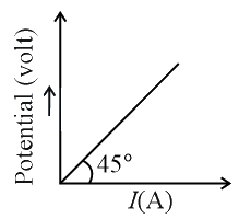 JEE Main/Numerical/Medium/Resistance and Resistivity/With diagram
- 68A AC source is connected to a lamp and an additional resistance in series (as shown in figure) to run the lamp at its peak brightness, then the value of (in ohm) will be
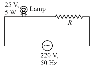 JEE Main/Numerical/Medium/Resistance and Resistivity/With diagram
- 69Two resistors and are connected in parallel. The equivalent resistance of their parallel combination will be :JEE Main/MCQ/Medium/Resistance and Resistivity
- 70The equivalent resistance of the given circuit between the terminals and is :
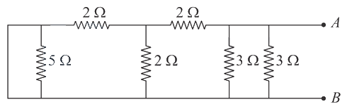 JEE Main/MCQ/Medium/Resistance and Resistivity/With diagram
- 71A square-shaped wire with a resistance of each side is bent to form a complete circle. The resistance between two diametrically opposite points of the circle in a unit of will is, _____.JEE Main/Numerical/Medium/Resistance and Resistivity
- 72The voltage drop across resistance in the given figure will be _______
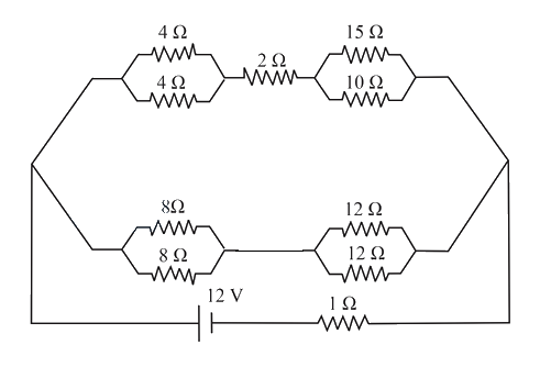 JEE Main/Numerical/Medium/Resistance and Resistivity/With diagram
- 73What equal length of an iron wire and a copper-nickel alloy wire, each of diameter connected parallel to give an equivalent resistance of ?
(Given resistivities of iron and copper-nickel alloy wire are and respectively)JEE Main/MCQ/Medium/Resistance and Resistivity - 74The resistance of a conductor at is and at is What will be the temperature coefficient of resistance of the conductor?JEE Main/MCQ/Medium/Resistance and Resistivity
- 75In the given figure switches and are in open condition. The resistance across when the switches and are closed is ________
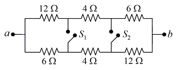 JEE Main/Numerical/Medium/Resistance and Resistivity/With diagram
- 76Two wires of same length and thickness having specific resistances and respectively are connected in parallel. The effective resistivity is . The value of to the nearest integer, is ___ .JEE Main/Numerical/Medium/Resistance and Resistivity
- 77A conducting wire of length , area of crosssection and electric resistivity is connected between the terminals of a battery. A potential difference is developed between its ends, causing an electric current. If the length of the wire of the same material is doubled and the area of cross-section is halved, the resultant current would be___JEE Main/MCQ/Medium/Resistance and Resistivity
- 78Consider four conducing materials copper, tungsten, mercury and aluminum with resistivity and respectively. Then :JEE Main/MCQ/Medium/Resistance and Resistivity
- 79Space between two concentric conducting spheres of radii and is filled with a medium of resistivity . The resistance between the two spheres will be:JEE Main/MCQ/Medium/Resistance and Resistivity
- 80In an experiment, the resistance of a material is plotted as a function of temperature (in some range). As shown in the figure, it is a straight line.
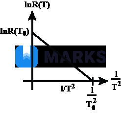
One may conclude thatJEE Main/MCQ/Medium/Resistance and Resistivity/With diagram - 81In the figure shown, what is the current (in Ampere) drawn from the battery? You are given:
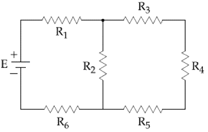 JEE Main/MCQ/Medium/Resistance and Resistivity/With diagram
- 82The actual value of resistance , shown in the figure is This is measured in an experiment as shown using the standard formula , where and are the readings of the voltmeter and ammeter, respectively. If the measured value of is less, then the internal resistance of the voltmeter is:
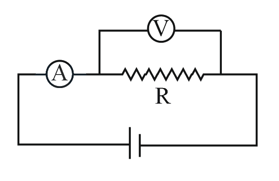 JEE Main/MCQ/Medium/Resistance and Resistivity/With diagram
- 83A uniform wire of length and radius has a resistance of . It is recast into a wire of radius . The resistance of new wire will be-JEE Main/MCQ/Medium/Resistance and Resistivity
- 84The resistance of an electrical toaster has a temperature dependence given by in its range of operation. At . The toaster is connected to a voltage source at and its temperature is raised at a constant rate from in . The total work done in raising the temperature is :
Note: This question was awarded as the bonus since all options were incorrect in the exam.JEE Main/MCQ/Medium/Resistance and Resistivity - 85The resistance of a wire is . It is bent at the middle by and both the ends are twisted together to make a shorter wire. The resistance of the new wire isJEE Main/MCQ/Medium/Resistance and Resistivity
- 86This question contains Statement-1 and Statement-2. Of the four choices given after the statements, choose the one that best describes the two statements.
Statement-1: The temperature dependence of resistance is usually given as . The resistance of a wire changes from to when its temperature is increased from to . This implies that .
Statement 2: is valid only when the change in the temperature is small and .JEE Main/MCQ/Medium/Resistance and Resistivity - 87The resistance of a wire is at and at . The resistance of the wire at will beJEE Main/MCQ/Medium/Resistance and Resistivity
- 88The resistance of a bulb filament is at a temperature of . If its temperature coefficient of resistance be per , its resistance will become at a temperature ofJEE Main/MCQ/Medium/Resistance and Resistivity
- 89A material ' ' has twice the specific resistance of ' '. A circular wire made of ' ' has twice the diameter of a wire made of ' '. Then for the two wires to have the same resistance, the ratio of their respective lengths must beJEE Main/MCQ/Medium/Resistance and Resistivity
- 90A piece of copper and another of germanium are cooled from room temperature to , the resistance ofJEE Main/MCQ/Medium/Resistance and Resistivity
- 91The length of a given cylindrical wire is increased by . Due to the consequent decrease in diameter the change in the resistance of the wire will beJEE Main/MCQ/Medium/Resistance and Resistivity
- 92A strip of copper and another of germanium are cooled from room temperature to . The resistance ofJEE Main/MCQ/Medium/Resistance and Resistivity
- 93By increasing the temperature, the specific resistance of a conductor and a semiconductorJEE Main/MCQ/Medium/Resistance and Resistivity
- 94Refer to the figure given below, current between terminals and is _____ A.
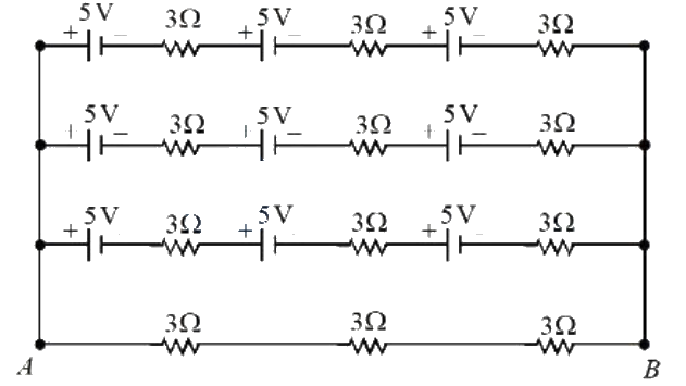 JEE Main/MCQ/Medium/Combination of Resistances/With diagram
- 95Two resistors of and are connected in series with a battery of V. A bulb rated at V, W is connected across the resistance. The potential drop across the bulb is _______ V.JEE Main/MCQ/Medium/Combination of Resistances
- 96A regular hexagon is formed by six wires each of resistance and the corners are joined to the centre by wires of same resistance. If the current enters at one corner and leaves at the opposite corner, the equivalent resistance of the hexagon between the two opposite corners will beJEE Main/MCQ/Medium/Combination of Resistances
- 97A wire of uniform resistance is bent into a circle of radius and another piece of wire with length is connected between points and as shown in figure. The equivalent resistance between points and is .
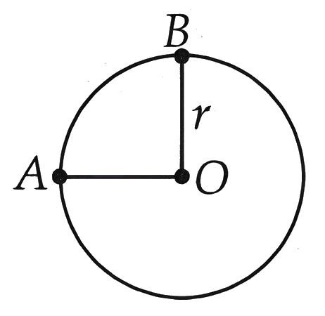 JEE Main/MCQ/Medium/Combination of Resistances/With diagram
- 98Two known resistances of and and one unknown resistance are connected in a circuit as shown in the figure. If the equivalent resistance between points and in the circuit is , then the value of is .
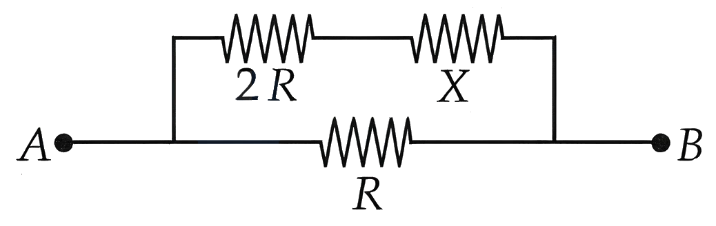 JEE Main/MCQ/Medium/Combination of Resistances/With diagram
- 99From the combination of resistors with resistance values and , which of the following combination is the best circuit to get an equivalent resistance of ?JEE Main/MCQ/Medium/Combination of Resistances
- 100Find the equivalent resistance between two ends of the following circuit
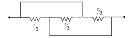 JEE Main/MCQ/Medium/Combination of Resistances/With diagram
- 101A wire of resistance R is bent into an equilateral triangle and an identical wire is bent into square. The ratio of resistance between the two end points of an edge of the triangle to that of the square is
OptionsJEE Main/MCQ/Medium/Combination of Resistances - 102To determine the resistance of a wire, a circuit is designed below. The characteristic curve for this circuit is plotted for the voltmeter and the ammeter readings as shown in figure. The value of is ______ .
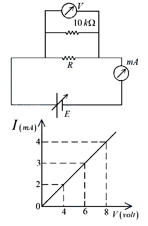 JEE Main/Numerical/Medium/Combination of Resistances/With diagram
- 103The effective resistance between and , if resistance of each resistor is , will be
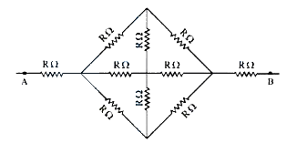 JEE Main/MCQ/Medium/Combination of Resistances/With diagram
- 104The equivalent resistance between and is :
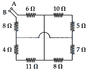 JEE Main/MCQ/Medium/Combination of Resistances/With diagram
- 105A wire of resistance is divided into 10 equal parts, resulting pairs. A combination of two parts are connected in parallel and so on. Now resulting pairs of parallel combination are connected in series. The equivalent resistance of final combination is _____ .JEE Main/Numerical/Medium/Combination of Resistances
- 106In the given figure and . Battery is ideal with emf . Equivalent resistant of the circuit and current supplied by battery are respectively :
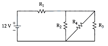 JEE Main/MCQ/Medium/Combination of Resistances/With diagram
- 107Twelve wires each having resistance are joined to form a cube. A battery of emf is joined across point and . The voltage difference between and is ______V.
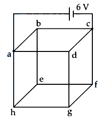 JEE Main/Numerical/Medium/Combination of Resistances/With diagram
- 108A network of four resistances is connected to battery, as shown in figure. The magnitude of voltage difference between the points and is __________ .
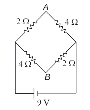 JEE Main/Numerical/Medium/Combination of Resistances/With diagram
- 109In the given circuit, the current through the battery will be
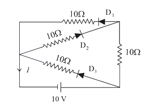 JEE Main/MCQ/Medium/Combination of Resistances/With diagram
- 110
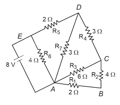
The current flowing through is :JEE Main/MCQ/Medium/Combination of Resistances/With diagram - 111 resistors each of resistance can be connected in such as to get maximum and minimum equivalent resistance. The ratio of maximum and minimum equivalent resistance will be________.JEE Main/Numerical/Medium/Combination of Resistances
- 112The equivalent resistance of the circuit shown below between points and is :
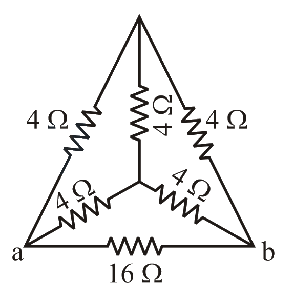 JEE Main/MCQ/Medium/Combination of Resistances/With diagram
- 113The equivalent resistance between and as shown in figure is:
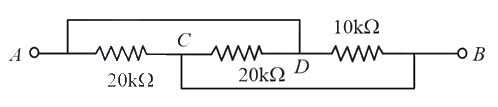 JEE Main/MCQ/Medium/Combination of Resistances/With diagram
- 114In the given circuit the value of is:
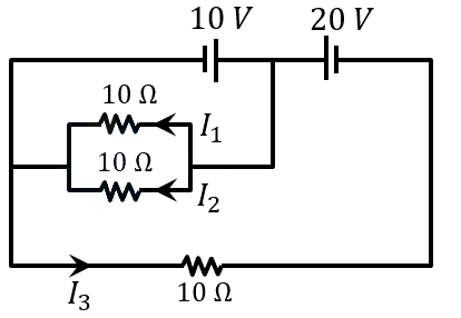 JEE Main/Numerical/Medium/Combination of Resistances/With diagram
- 115Equivalent resistance between the adjacent corners of a regular -sided polygon of uniform wire of resistance would be :JEE Main/MCQ/Medium/Combination of Resistances
- 116The equivalent resistance between of the network shown in figure:
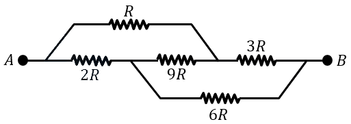 JEE Main/MCQ/Medium/Combination of Resistances/With diagram
- 117If the potential difference between and is zero, the value of is . The value of is ______.
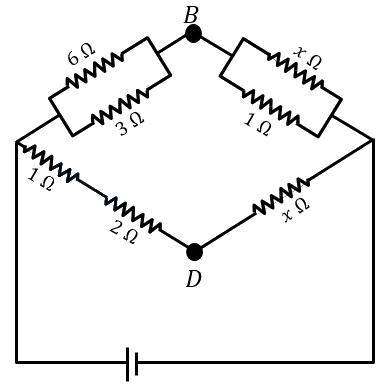 JEE Main/Numerical/Medium/Combination of Resistances/With diagram
- 118The equivalent resistance between is _______.
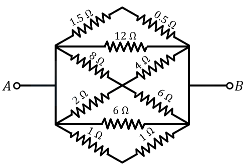 .JEE Main/MCQ/Medium/Combination of Resistances/With diagram
- 119In the following circuit, the magnitude of current , is ______ .
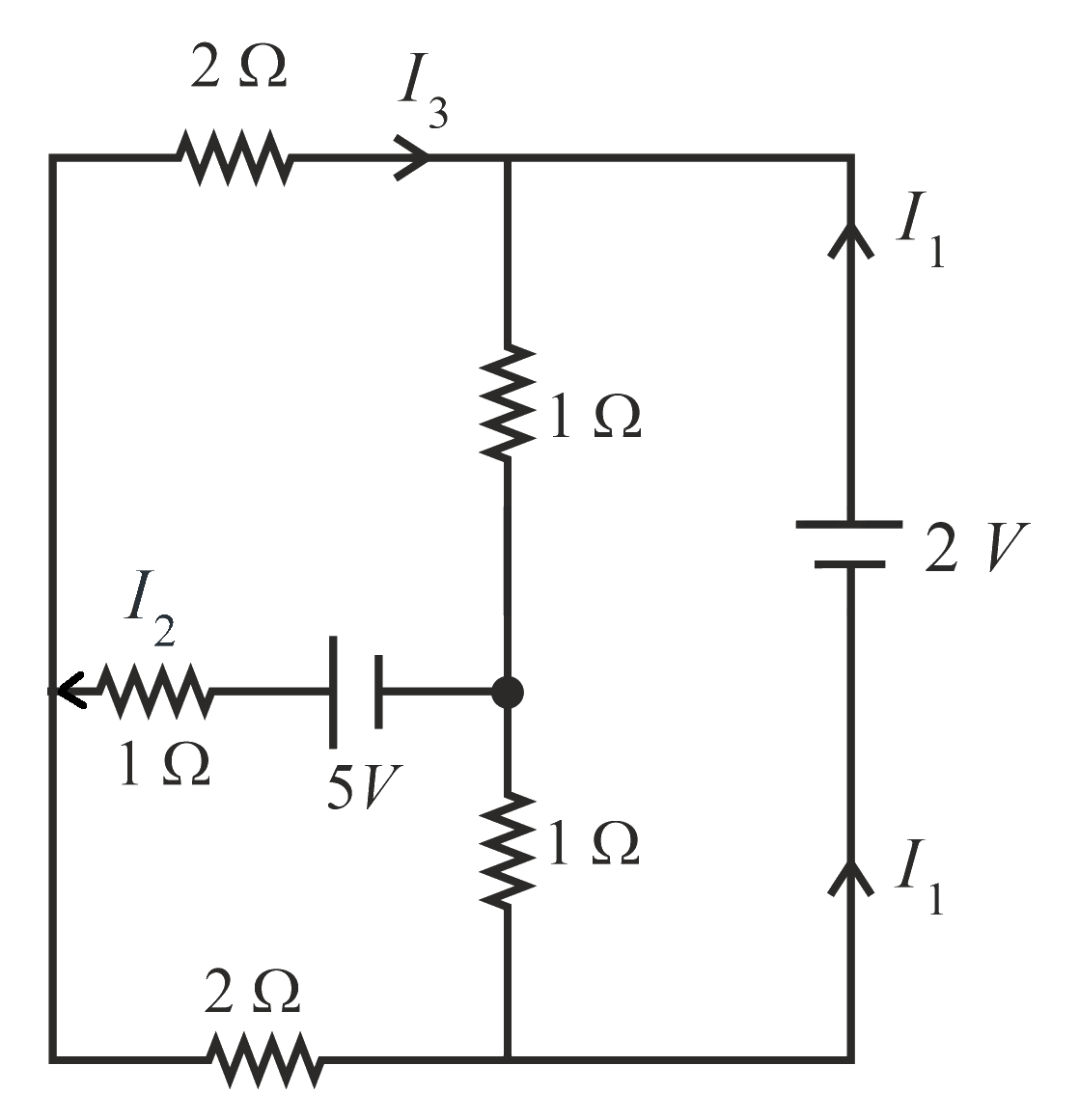 JEE Main/Numerical/Medium/Combination of Resistances/With diagram
- 120In the given circuit, the equivalent resistance between the terminal A and B is ____
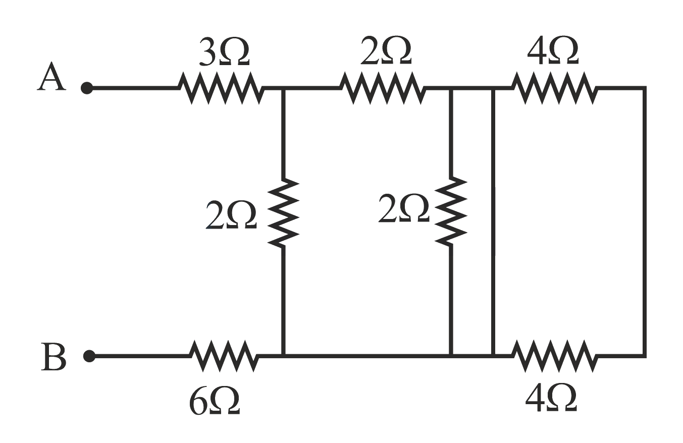 JEE Main/Numerical/Medium/Combination of Resistances/With diagram
- 121A cell of emf is connected across series combination of two resistors each of resistance. A voltmeter of resistance is used to measure the potential difference across each resistor. The reading of the voltmeter will be:JEE Main/MCQ/Medium/Combination of Resistances
- 122As shown in the figure, a network of resistors is connected to a battery of with an internal resistance of . The currents through the resistors and are and respectively. The values of and are:
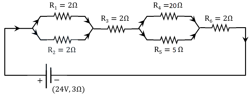 JEE Main/MCQ/Medium/Combination of Resistances/With diagram
- 123The current I flowing through the given circuit will be _____ .
 JEE Main/Numerical/Medium/Combination of Resistances/With diagram
- 124An electrical bulb rated , is connected in series with another bulb rated , . If the voltage across combination is , the power consumed by the bulb will be about _____ .JEE Main/Numerical/Medium/Combination of Resistances
- 125A current of flows in the circuit as shown in figure. The value of potential difference between the points and will be
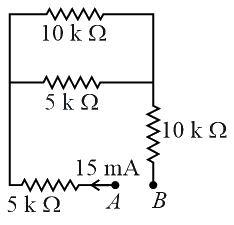 JEE Main/MCQ/Medium/Combination of Resistances/With diagram
- 126Eight copper wire of length and diameter d are joined in parallel to form a single composite conductor of resistance . If a single copper wire of length have the same resistance then its diameter will be _____ .JEE Main/Numerical/Medium/Combination of Resistances
- 127In the given figure, the value of will be _____ .
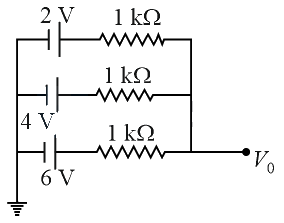 JEE Main/Numerical/Medium/Combination of Resistances/With diagram
- 128Two resistors are connected in series across a battery as shown in figure. If a voltmeter of resistance is used to measure the potential difference across resister, the reading of the voltmeter will be _____
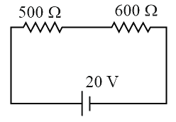 JEE Main/Numerical/Medium/Combination of Resistances/With diagram
- 129All resistances in figure are each. The value of current '' is . The value of is _____ .
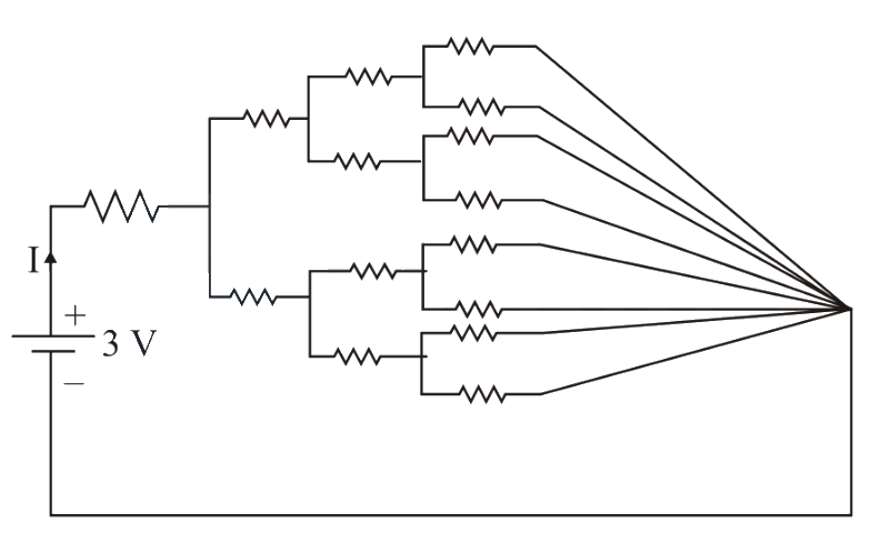 JEE Main/Numerical/Medium/Combination of Resistances/With diagram
- 130In the given circuit 'a' is an arbitrary constant. The value of for which the equivalent circuit resistance is minimum, will be . The value of is _____ .
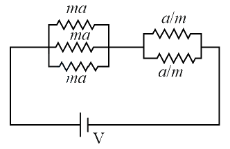 JEE Main/Numerical/Medium/Combination of Resistances/With diagram
- 131Find the equivalent resistance between point and
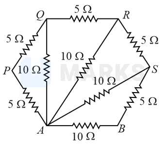 JEE Main/MCQ/Medium/Combination of Resistances/With diagram
- 132An aluminium wire is stretched to make its length, larger. The percentage change in resistance isJEE Main/MCQ/Medium/Combination of Resistances
- 133The length of a given cylindrical wire is increased to double of its original length. The percentage increase in the resistance of the wire will be _____ JEE Main/Numerical/Medium/Combination of Resistances
- 134What will be the most suitable combination of three resistors so that is equivalent resistance of combination?JEE Main/MCQ/Medium/Combination of Resistances
- 135The ratio of the equivalent resistance of the network (shown in figure) between the points and when switch is open and switch is closed is . The value of is
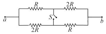 JEE Main/Numerical/Medium/Combination of Resistances/With diagram
- 136First, a set of equal resistors of each are connected in series to a battery of E.M.F. and internal resistance A current is observed to flow. Then, the resistors are connected in parallel to the same battery. It is observed that the current is increased times, then the value of is ___________.JEE Main/Numerical/Medium/Combination of Resistances
- 137If you are provided a set of resistances, and Connect these resistances to obtain an equivalent resistance of .JEE Main/MCQ/Medium/Combination of Resistances
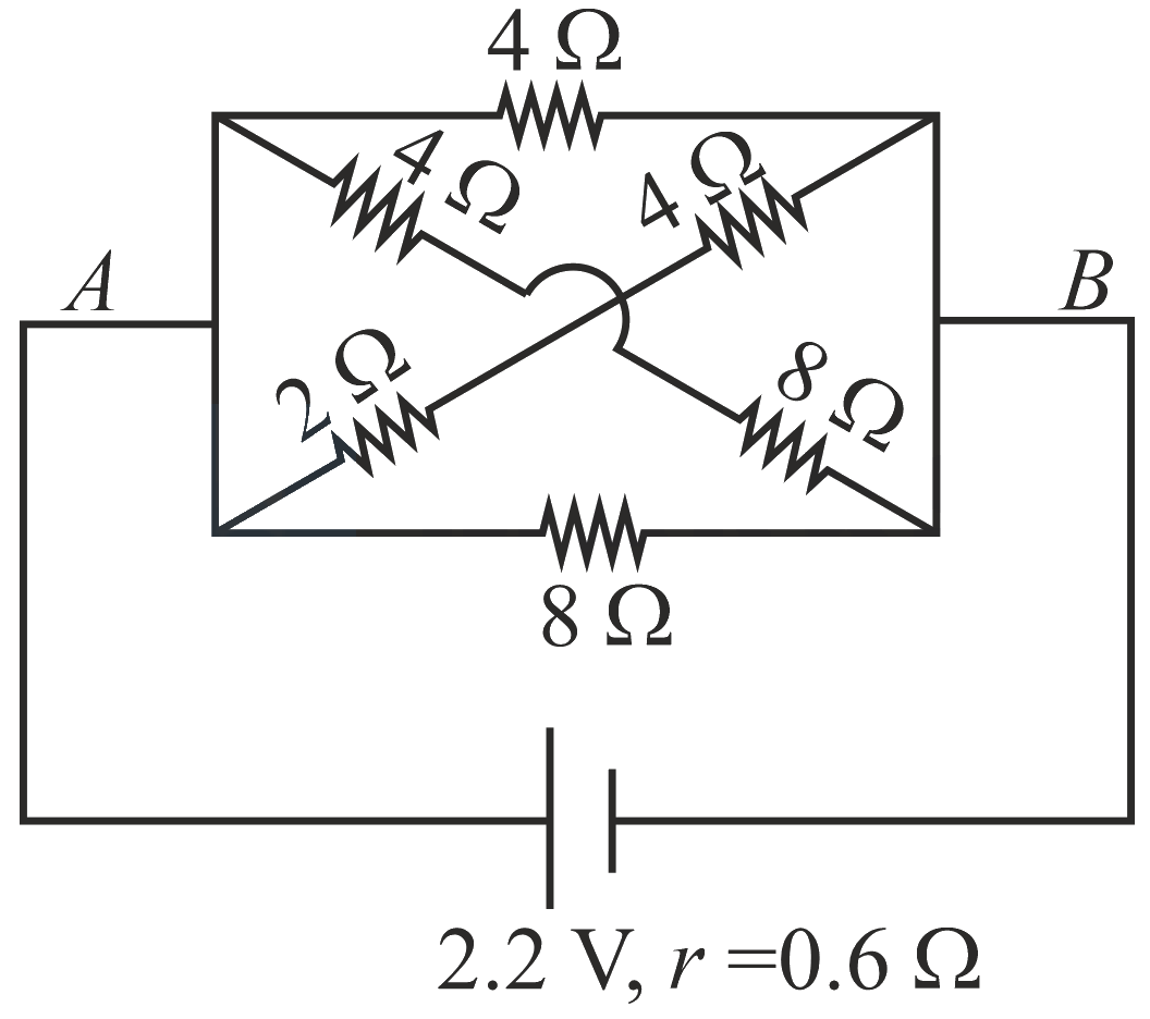
- 138In the given figure, the emf of the cell is and if internal resistance is . Calculate the power dissipated in the whole circuit:
 JEE Main/MCQ/Medium/Combination of Resistances/With diagram
- 139A Copper rod of length and cross-sectional area is joined with a similar Aluminium rod as shown in figure. Find the resistance of the combination between the ends and
(Take resistivity of Copper , Resistivity of aluminium )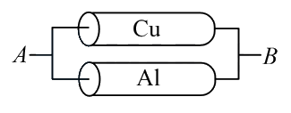 JEE Main/MCQ/Medium/Combination of Resistances/With diagram
- 140The voltage across the resistor in the given circuit is volt.
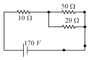
The value of to the nearest integer is _____.JEE Main/Numerical/Medium/Combination of Resistances/With diagram - 141The equivalent resistance of series combination of two resistors is When they are connected in parallel, the equivalent resistance is If then the minimum value for is ______.
(Round off to the Nearest Integer)JEE Main/Numerical/Medium/Combination of Resistances - 142A current of enters one corner of an equilateral triangle having wires of resistance each and leaves by the corner The currents in ampere is
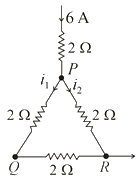 JEE Main/Numerical/Medium/Combination of Resistances/With diagram
- 143Four resistance and make the arms of a quadrilateral . Across is a battery of emf and internal resistance negligible. The potential difference across in is __________
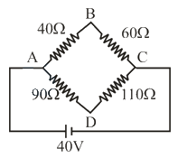 JEE Main/Numerical/Medium/Combination of Resistances/With diagram
- 144Two resistors and are connected in series across a battery. The potential difference measured by a voltmeter of across resistor is close to:JEE Main/MCQ/Medium/Combination of Resistances
- 145An ideal cell of emf is connected in circuit shown in figure. Each resistance is . The potential difference (in ) across the capacitor when it is fully charged is _____________
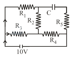 JEE Main/Numerical/Medium/Combination of Resistances/With diagram
- 146In the given circuit diagram, a wire is joining points B and D. The current in this wire is:
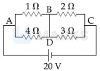 JEE Main/MCQ/Medium/Combination of Resistances/With diagram
- 147The series combination of two batteries, both of the same emf but different internal resistance of and is connected to the parallel combination of two resistors and The voltage difference across the battery of internal resistance is zero, the value of (in is____JEE Main/Numerical/Medium/Combination of Resistances
- 148In the figure, potential difference between and is:
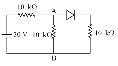 JEE Main/MCQ/Medium/Combination of Resistances/With diagram
- 149The current (in ) flowing through resistor in the following circuit is:
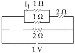 JEE Main/MCQ/Medium/Combination of Resistances/With diagram
- 150The resistive network shown below is connected to a source of The power consumed by the network is Watt. The value of is:
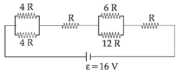 JEE Main/MCQ/Medium/Combination of Resistances/With diagram
- 151A metal wire of resistance is elongated to make a uniform wire of double its previous length. This new wire is now bent and the ends joined to make a circle. If two points on this circle make an angle at the center, the equivalent resistance between these two points will be:JEE Main/MCQ/Medium/Combination of Resistances
- 152Determine the charge on the capacitor in the following circuit:
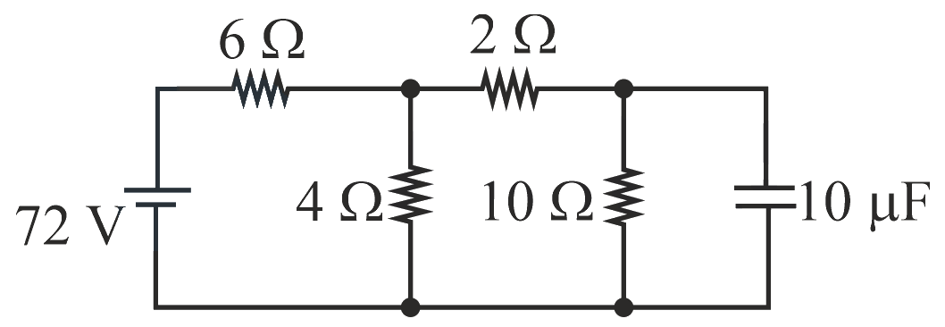 JEE Main/MCQ/Medium/Combination of Resistances/With diagram
- 153A wire of resistance is bent to form a square as shown in the figure. The effective resistance between and is:
( is mid-point of arm )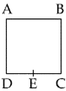 JEE Main/MCQ/Medium/Combination of Resistances/With diagram
- 154A uniform metallic wire has a resistance of and is bent into an equilateral triangle. Then, the resistance between any two vertices of the triangle is:JEE Main/MCQ/Medium/Combination of Resistances
- 155In the given circuit the internal resistance of the cell is negligible. If and and the reading of an ideal voltmeter across is then the value of will be:
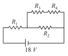 JEE Main/MCQ/Medium/Combination of Resistances/With diagram
- 156In the given circuit all resistance is of the value of ohm each. The equivalent resistance between and is:
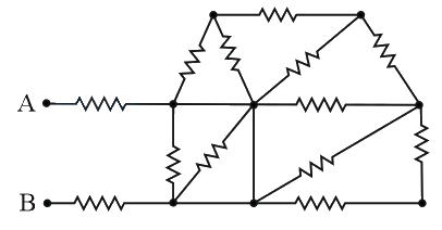 JEE Main/MCQ/Medium/Combination of Resistances/With diagram
- 157In the given circuit all resistances are of value ohm each. The equivalent resistance between and is:
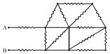 JEE Main/MCQ/Medium/Combination of Resistances/With diagram
- 158
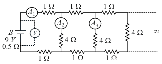
A battery with an internal resistance of is connected across an infinite network, as shown in the figure. All ammeters and voltmeter are ideal.
Choose the correct statement.JEE Main/MCQ/Medium/Combination of Resistances/With diagram - 159
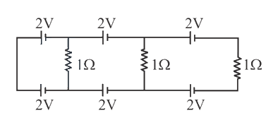
In the above circuit the current in each resistance is:JEE Main/MCQ/Medium/Combination of Resistances/With diagram - 160In the electric network shown, when no current flows through the resistor in the arm EB, the potential difference between the points A and D will be:
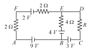 JEE Main/MCQ/Medium/Combination of Resistances/With diagram
- 161Six equal resistances are connected between points and as shown in figure. Then net resistance will be maximum between :
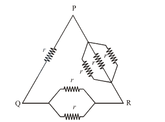 JEE Main/MCQ/Medium/Combination of Resistances/With diagram
- 162A letter is constructed of a uniform wire with resistance per , The sides of the letter are and the cross piece in the middle is long. The apex angle is 60 . The resistance between the ends of the legs is close to:JEE Main/MCQ/Medium/Combination of Resistances
- 163The current drawn from the 5 volt source will be
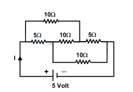 JEE Main/MCQ/Medium/Combination of Resistances/With diagram
- 164An electric current is passed through a circuit containing two wires of the same material, connected in parallel. If the length and radii of the wires are in the ratio of and , then the ratio of the currents passing through the wire will beJEE Main/MCQ/Medium/Combination of Resistances
- 165The resistance of the series combination of two resistances is . When they are joined in parallel through total resistance is . If , then the minimum possible value of isJEE Main/MCQ/Medium/Combination of Resistances
- 166The total current supplied to the circuit by the battery is
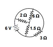 JEE Main/MCQ/Medium/Combination of Resistances/With diagram
- 167A 3 volt battery with negligible internal resistance is connected in a circuit as shown in the figure. The current , in the circuit will be
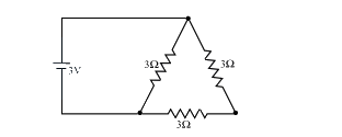 JEE Main/MCQ/Medium/Combination of Resistances/With diagram
- 168Two cells of emfs V and V and internal resistance and , respectively connected in parallel, gave a current of A through an external resistance. If the polarity of one cell is reversed, then value of current through the external resistance will be A. The value of is __________.JEE Main/Numerical/Medium/Electric Cell or Battery
- 169When an external resistance of is connected across terminals of a cell, a current of flows through it. When the resistor is replaced by a resistor, a current of flows through it. The internal resistance of the cell is _______ .JEE Main/Numerical/Medium/Electric Cell or Battery
- 170For the two cells having same EMF and internal resistance , the current passing through the external resistor is same when both the cells are connected either in parallel or in series. The value of internal resistance is .JEE Main/MCQ/Medium/Electric Cell or Battery
- 171Two cells of emf 1 V and 2 V and internal resistance and , respectively, are connected in series with an external resistance of . The total current in the circuit is . Now the same two cells in parallel configuration are connected to same external resistance. In this case, the total current drawn is . The value of is . The value of is _____.JEE Main/Numerical/Medium/Electric Cell or Battery
- 172What is the current through the battery in the circuit shown below
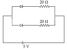 JEE Main/MCQ/Medium/Electric Cell or Battery/With diagram
- 173Given below are two statements :
Statement-I : The equivalent emf of two nonideal batteries connected in parallel is smaller than either of the two emfs.
Statement-II : The equivalent internal resistance of two nonideal batteries connected in parallel is smaller than the internal resistance of either of the two batteries.
In the light of the above statements, choose the correct answer from the options given below.JEE Main/MCQ/Medium/Electric Cell or Battery - 174In the given circuit, the terminal potential difference of the cell is :
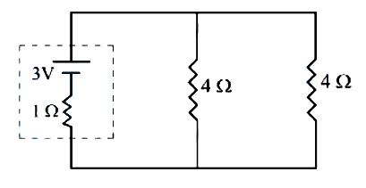 JEE Main/MCQ/Medium/Electric Cell or Battery/With diagram
- 175Two cells are connected in opposition as shown. Cell is of emf and internal resistance; the cell is of emf and internal resistance. The terminal potential difference of cell is ______ .
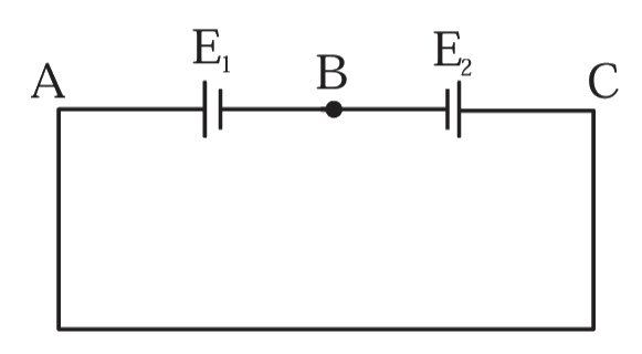 JEE Main/Numerical/Medium/Electric Cell or Battery/With diagram
- 176Two identical cells each of emf are connected in series across a resistance. An ideal voltmeter connected across resistance reads . The internal resistance of each cell is _____ .JEE Main/Numerical/Medium/Electric Cell or Battery
- 177In the circuit diagram shown in figure given below, the current flowing through resistance is . The value of is ________.
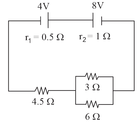 JEE Main/Numerical/Medium/Electric Cell or Battery/With diagram
- 178For the given circuit, in the steady state, _____ .
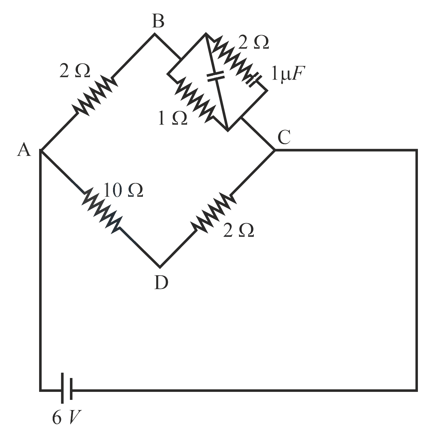 JEE Main/Numerical/Medium/Electric Cell or Battery/With diagram
- 179Two identical cells, when connected either in parallel or in series gives same current in an external resistance . The internal resistance of each cell will be ______ .JEE Main/Numerical/Medium/Electric Cell or Battery
- 180Two cells are connected between points and as shown. Cell 1 has emf of and internal resistance of . Cell 2 has emf of and internal resistance of . An external resistor of is connected across and . The current flowing through will be ______ .
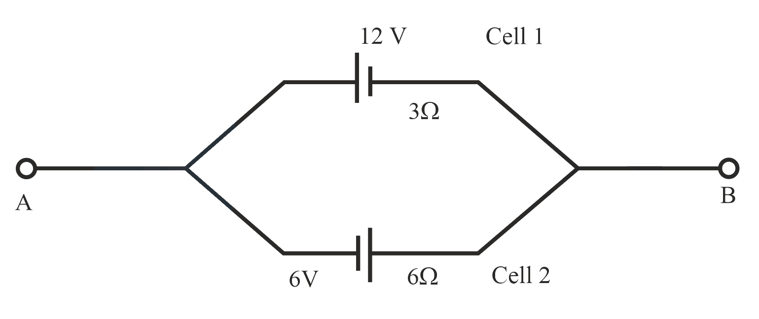 JEE Main/Numerical/Medium/Electric Cell or Battery/With diagram
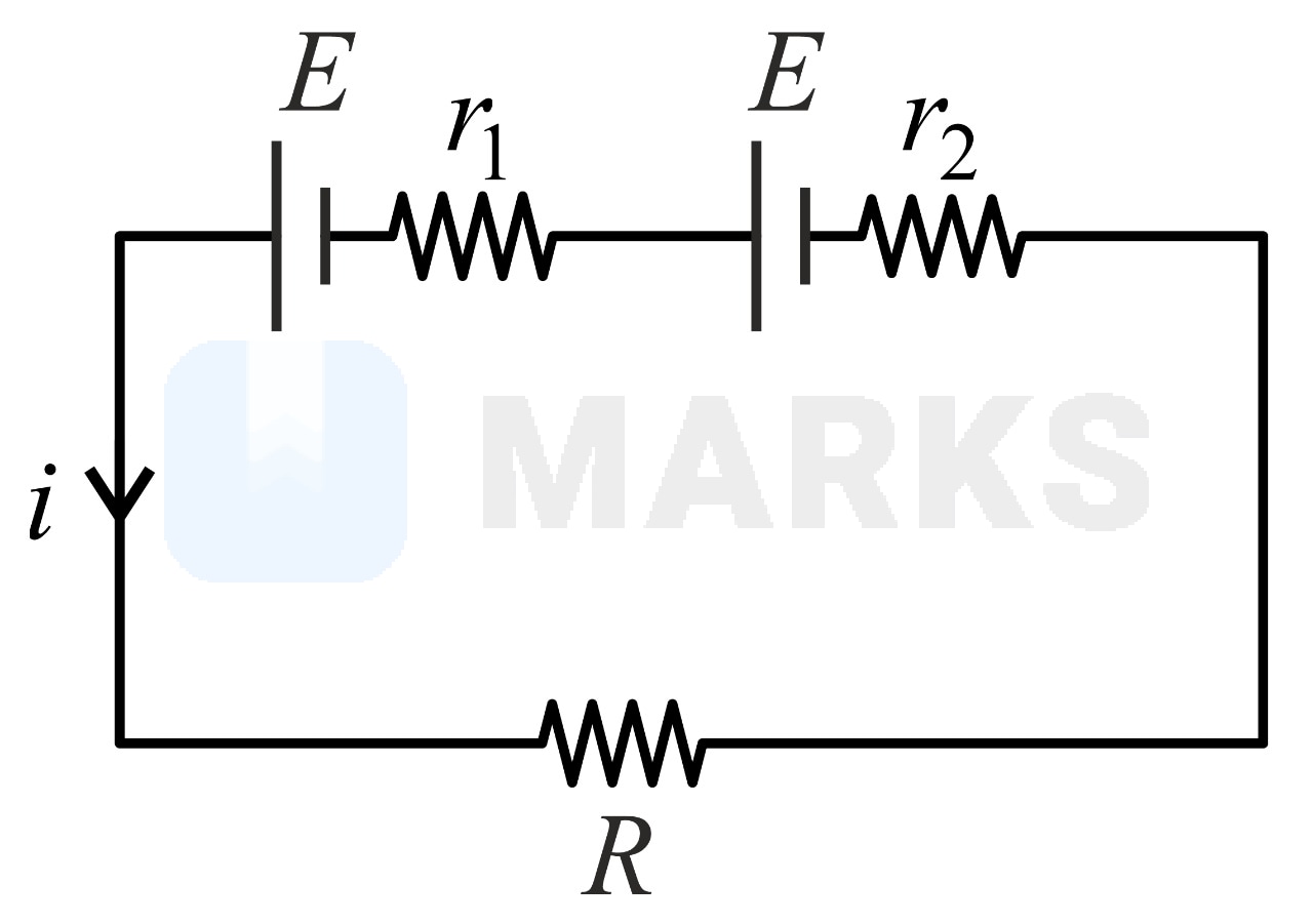
- 181Two sources of equal emfs are connected in series. This combination is connected to an external resistance . The internal resistances of the two sources are and . If the potential difference across the source of internal resistance is zero then the value of will beJEE Main/MCQ/Medium/Electric Cell or Battery
- 182The combination of two identical cells, whether connected in series or parallel combination provides the same current through an external resistance of . The value of internal resistance of each cell isJEE Main/MCQ/Medium/Electric Cell or Battery
- 183Two cells of the same EMF but different internal resistances and are connected in series with an external resistance as shown in the figure. The terminal potential difference across, the second cell is found to be zero. The external resistance must then be:
 JEE Main/MCQ/Medium/Electric Cell or Battery/With diagram
- 184Two identical cells each of emf are connected in parallel across a parallel combination of two resistors each of resistance . A voltmeter connected in the circuit measures . The internal resistance of each cell is :JEE Main/MCQ/Medium/Electric Cell or Battery
- 185Five identical cells each of internal resistance and emf are connected in series and in parallel with an external resistance For what value of current in series and parallel combination will remain the same?JEE Main/MCQ/Medium/Electric Cell or Battery
- 186In the given figure, a battery of emf is connected across a conductor of length and different area of cross-sections having radii and
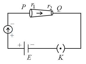
Choose the correct option as one moves from to .JEE Main/MCQ/Medium/Electric Cell or Battery/With diagram - 187In an electric circuit, a call of certain emf provides a potential difference of across a load resistance of However, it provides a potential difference of across a load resistance of The emf of the cell is given by Then the value of is JEE Main/Numerical/Medium/Electric Cell or Battery
- 188Two cells of emf and with internal resistance and respectively are connected in series to an external resistor (see figure). The value of at which the potential difference across the terminals of the first cell becomes zero is
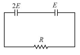 JEE Main/MCQ/Medium/Electric Cell or Battery/With diagram
- 189A cell of emf and internal resistance is connected with another cell of emf and internal resistance (as shown in the figure). The potential difference across points and is:
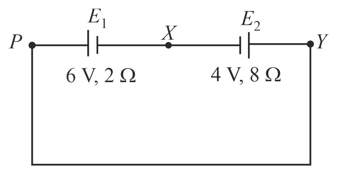 JEE Main/MCQ/Medium/Electric Cell or Battery/With diagram
- 190A battery of is connected to a resistor dissipating of power. If the terminal voltage of the battery is , the power dissipated within the internal resistance is:JEE Main/MCQ/Medium/Electric Cell or Battery
- 191To verify Ohm’s law, a student connects the voltmeter across the battery as shown in the figure. The measured voltage is plotted as a function of the current, and the following graph is obtained:
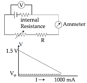
If is almost zero, identify the correct statement:JEE Main/MCQ/Medium/Electric Cell or Battery/With diagram - 192In the given circuit, an ideal voltmeter connected across the resistance reads . The internal resistance , of each cell is:
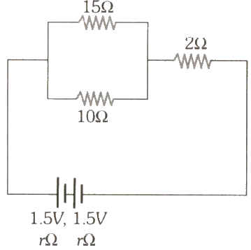 JEE Main/MCQ/Medium/Electric Cell or Battery/With diagram
- 193For the circuit shown, with , , and the potential difference between the points and is approximately ( ):
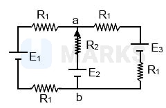 JEE Main/MCQ/Medium/Electric Cell or Battery/With diagram
- 194Two batteries with e.m.f. and are connected in parallel across a load resistor of . The internal resistance of the two batteries are and respectively. The voltage across the load lies between,JEE Main/MCQ/Medium/Electric Cell or Battery
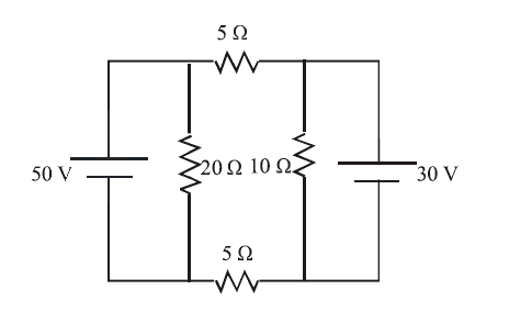
- 195
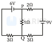
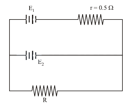
In the circuit shown, the current in the resistor is:JEE Main/MCQ/Medium/Electric Cell or Battery/With diagram - 196In the circuit shown, current (in A) through and batteries are, respectively:
 JEE Main/MCQ/Medium/Electric Cell or Battery/With diagram
- 197A d.c. main supply of e.m.f. is connected across a storage battery of e.m.f. through a resistance of . The battery terminals are connected to external resistance . The minimum value of , so that a current passes through the battery to charge it is:JEE Main/MCQ/Medium/Electric Cell or Battery
- 198A dc source of emf and internal resistance , a storage battery of emf and an external resistance are connected as shown in figure. For what value of R no current will pass through the battery?
 JEE Main/MCQ/Medium/Electric Cell or Battery/With diagram
- 199The supply voltage to a room is . The resistance of the lead wires is . A bulb is already switched on. What is the decrease of voltage across the bulb, when a heater is switched on in parallel to the bulb?JEE Main/MCQ/Medium/Electric Cell or Battery
- 200In the circuit, the galvanometer shows zero deflection. If the batteries and have negligible internal resistance, the value of the resistor will be
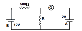 JEE Main/MCQ/Medium/Electric Cell or Battery/With diagram
- 201The negative pole of a Daniell cell, sending a constant current through a circuit, decreases in mass by in 30 minutes. If the electrochemical equivalent of and are and respectively, the increase in the mass of the positive Cu pole in this time isJEE Main/MCQ/Medium/Electric Cell or Battery
- 202The stored charge in the capacitor in steady state of the following circuit is ________ C.
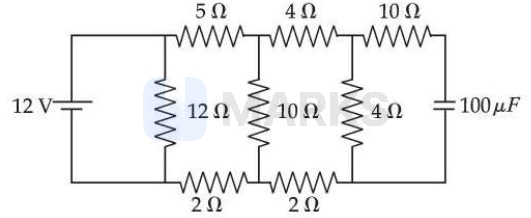 JEE Main/Numerical/Medium/Kirchoffs Laws/With diagram
- 203Refer to the circuit diagram given below. The heat generated across the resistance in second is J. The value of is _______. (Nearest integer)
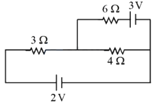 JEE Main/Numerical/Medium/Kirchoffs Laws/With diagram
- 204Under steady state condition the potential difference across the capacitor in the circuit is _______ V.
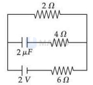 JEE Main/MCQ/Medium/Kirchoffs Laws/With diagram
- 205Refer to the figure given below. The values of , and are __________.
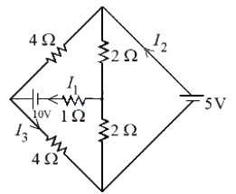 JEE Main/MCQ/Medium/Kirchoffs Laws/With diagram
- 206The voltage and the current between and points shown in the circuit are _____.
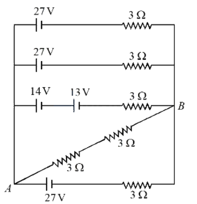 JEE Main/MCQ/Medium/Kirchoffs Laws/With diagram
- 207The reading of the ammeter in steady state in the following circuit (assuming negligible internal resistance of the ammeter) is A.
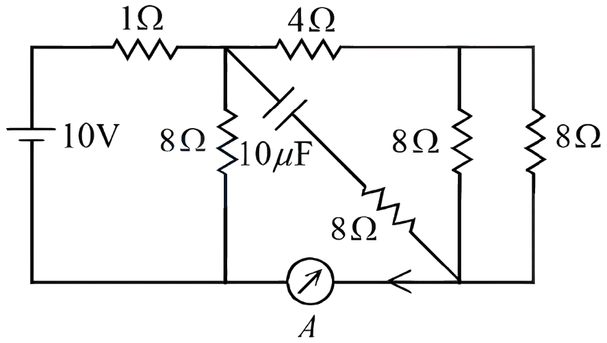 JEE Main/MCQ/Medium/Kirchoffs Laws/With diagram
- 208The value of current I in the electrical circuit as given below, when potential at A is equal to the potential at B, will be ____ A.
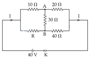 JEE Main/Numerical/Medium/Kirchoffs Laws/With diagram
- 209The net current flowing in the given circuit is_______ A.
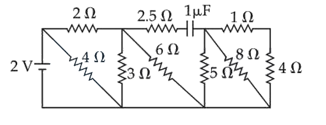 JEE Main/Numerical/Medium/Kirchoffs Laws/With diagram
- 210The current flowing through the resistor is A. The value of is _________
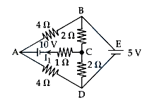 JEE Main/Numerical/Medium/Kirchoffs Laws/With diagram
- 211A potential divider circuit is shown in figure. The output voltage is
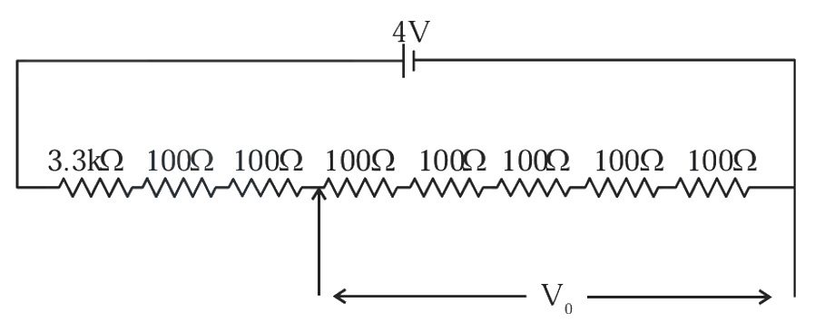 JEE Main/MCQ/Medium/Kirchoffs Laws/With diagram
- 212Figure shows a part of an electric circuit. The potentials at points and are and respectively. The current through the resistor will be,
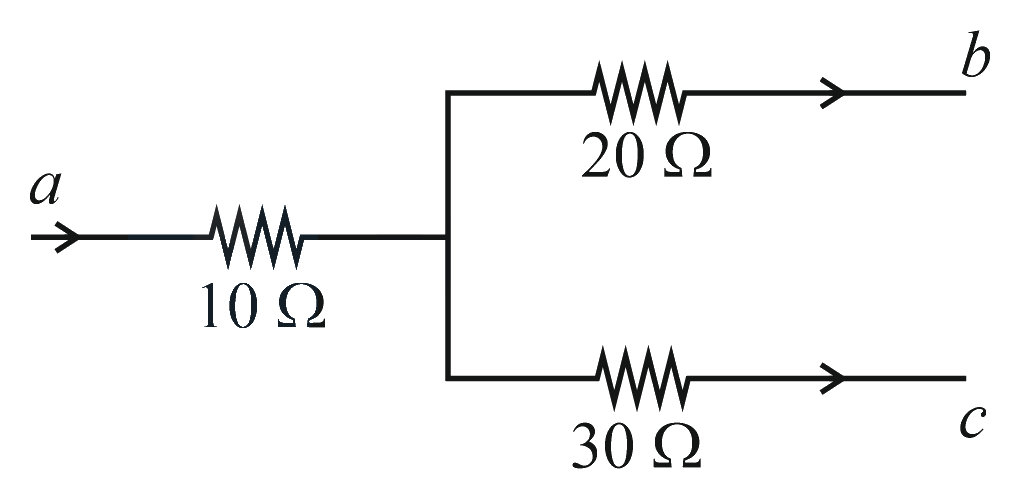 JEE Main/MCQ/Medium/Kirchoffs Laws/With diagram
- 213A wire is bent to form a square loop. A supply having an internal resistance of is connected across one of its sides. The potential drop across the diagonals of the square loop is __________.JEE Main/Numerical/Medium/Kirchoffs Laws
- 214
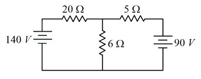
The value of current in the resistance is:JEE Main/MCQ/Medium/Kirchoffs Laws/With diagram - 215In the figure shown, the current in the battery is close to :
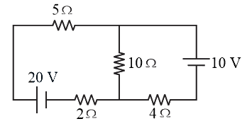 JEE Main/MCQ/Medium/Kirchoffs Laws/With diagram
- 216In the circuit, given in the figure currents in different branches and value of one resistor are shown. Then potential at point with respect to the point is:
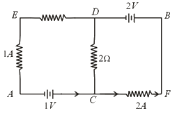 JEE Main/MCQ/Medium/Kirchoffs Laws/With diagram
- 217In the given circuit diagram, the currents, and are flowing as shown. The currents and respectively, are:
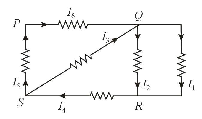 JEE Main/MCQ/Medium/Kirchoffs Laws/With diagram
- 218In the circuit shown, the potential difference between and is
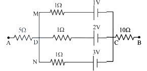 JEE Main/MCQ/Medium/Kirchoffs Laws/With diagram
- 219In the given circuit the cells have zero internal resistance. The currents (in amperes) passing through resistance and respectively, are:
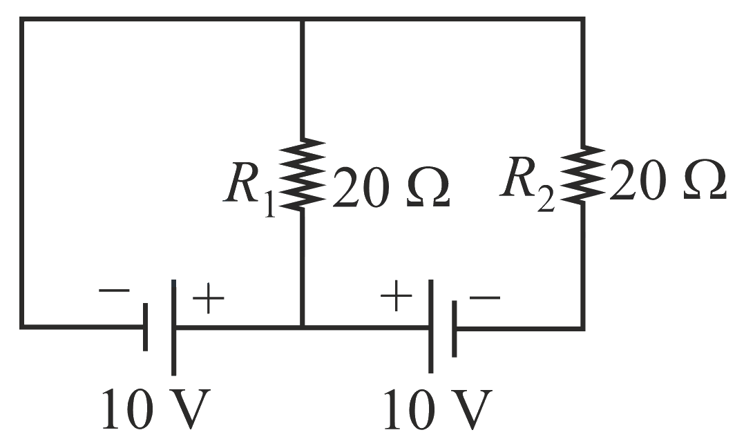 JEE Main/MCQ/Medium/Kirchoffs Laws/With diagram
- 220When the switch in the circuit shown, is closed, then the value of current will be:
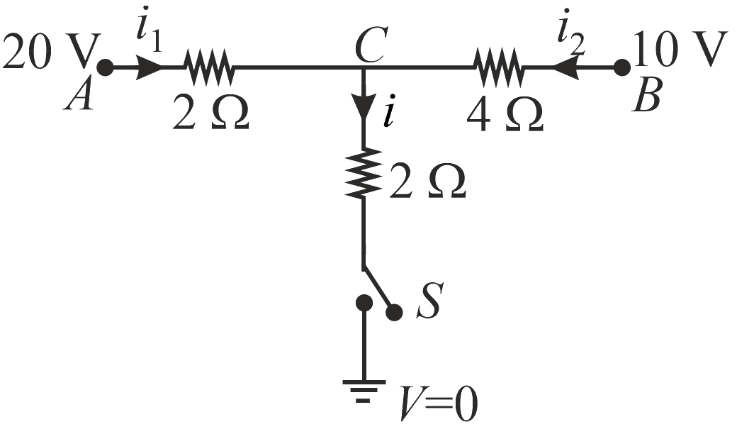 JEE Main/MCQ/Medium/Kirchoffs Laws/With diagram
- 221The circuit shown here has two batteries of and and three resistors and and a capacitor of .
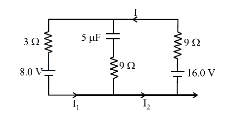
How much is the current in the circuit in steady state?JEE Main/MCQ/Medium/Kirchoffs Laws/With diagram - 222A battery with internal resistance and a battery with internal resistance are connected to a resistor as shown in the figure. The current in the resistor is
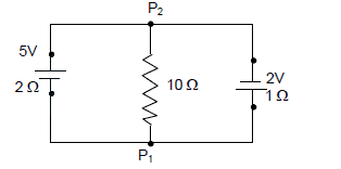 JEE Main/MCQ/Medium/Kirchoffs Laws/With diagram
- 223The Kirchhoff's first law and second law , where the symbols have their usual meanings, are respectively based onJEE Main/MCQ/Medium/Kirchoffs Laws
- 224An electric power line having total resistance of , delivers 1 kW of power at 250 V. The percentage efficiency of transmission line is .JEE Main/MCQ/Medium/Electric Power and Heating Effect of Current
- 225There are ' ' number of identical electric bulbs, each is designed to draw a power independently from the mains supply. They are now joined in series across the main supply. The total power drawn by the combination is :JEE Main/MCQ/Medium/Electric Power and Heating Effect of Current
- 226A motor operating on 100 V draws a current of 1 A. If the efficiency of the motor is , then the loss of power in units of isJEE Main/MCQ/Medium/Electric Power and Heating Effect of Current
- 227The battery of a mobile phone is rated as 4.2 V , 5800 mAh. How much energy is stored in it when fully charged ?JEE Main/MCQ/Medium/Electric Power and Heating Effect of Current
- 228A heater is designed to operate with a power of in a line. It is connected in combination with a resistance of and a resistance , to a mains as shown in figure. For the heater to operate at , the value of should be _____.
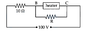 JEE Main/Numerical/Medium/Electric Power and Heating Effect of Current/With diagram
- 229Water boils in an electric kettle in 20 minutes after being switched on. Using the same main supply, the length of the heating element should be _____ to _____ times of its initial length if the water is to be boiled in 15 minutes.JEE Main/MCQ/Medium/Electric Power and Heating Effect of Current
- 230The number of electrons flowing per second in the filament of a bulb operating at is : Given JEE Main/MCQ/Medium/Electric Power and Heating Effect of Current
- 231The ratio of heat dissipated per second through the resistance and in the circuit given below is :
 JEE Main/MCQ/Medium/Electric Power and Heating Effect of Current/With diagram
- 232An electric bulb rated is connected across a supply. The power dissipation of the bulb is:JEE Main/MCQ/Medium/Electric Power and Heating Effect of Current
- 233In the following circuit, the battery has an emf of and an internal resistance of . The power consumption in the entire circuit is ______ .
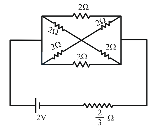 JEE Main/Numerical/Medium/Electric Power and Heating Effect of Current/With diagram
- 234By what percentage will the illumination of the lamp decrease if the current drops by ?JEE Main/MCQ/Medium/Electric Power and Heating Effect of Current
- 235When a potential difference is applied across a wire of resistance , it dissipates energy at a rate If the wire is cut into two halves and these halves are connected mutually parallel across the same supply, the energy dissipation rate will become:JEE Main/MCQ/Medium/Electric Power and Heating Effect of Current
- 236An electric toaster has resistance of at room temperature . The toaster is connected to a supply. If the current flowing through it reaches , the temperature attained by toaster is around: (if )JEE Main/MCQ/Medium/Electric Power and Heating Effect of Current
- 237A potential is applied across a uniform wire of resistance The power dissipation is The wire is then cut into two equal halves and a potential of is applied across the length of each half. The total power dissipation across two wires is The ratio of is The value of is _____.JEE Main/Numerical/Medium/Electric Power and Heating Effect of Current
- 238Different combination of resistors of equal resistance are shown in the figures. The increasing order for power dissipation is:
(A)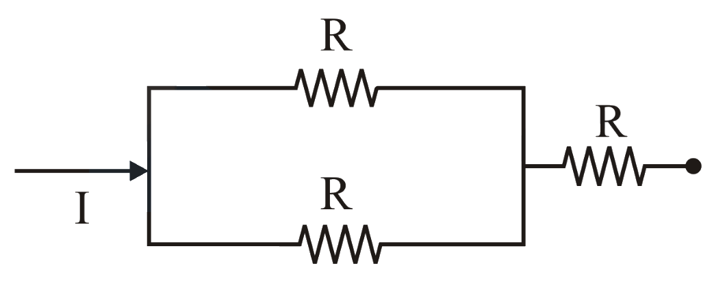
(B)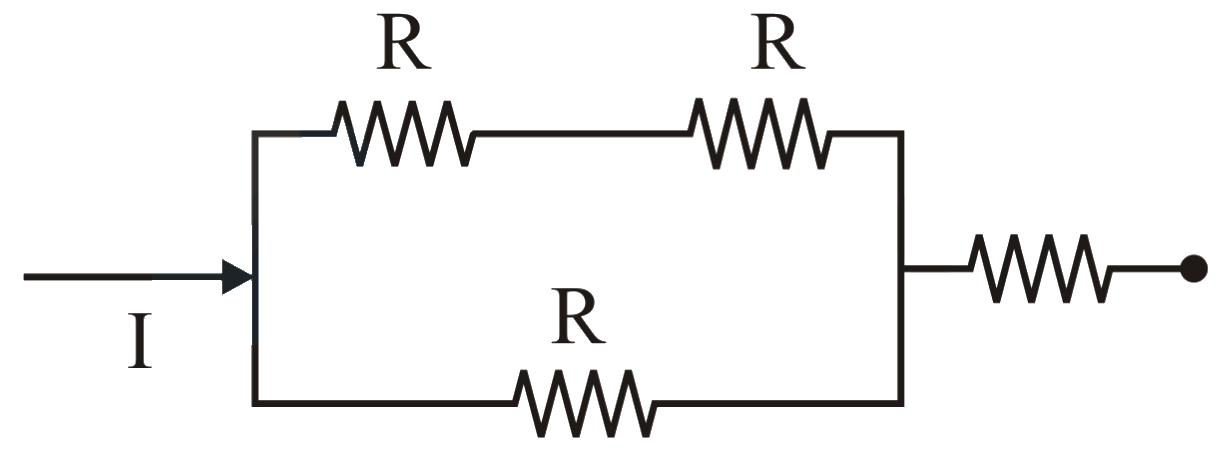
(C)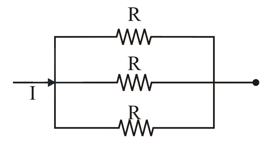
(D)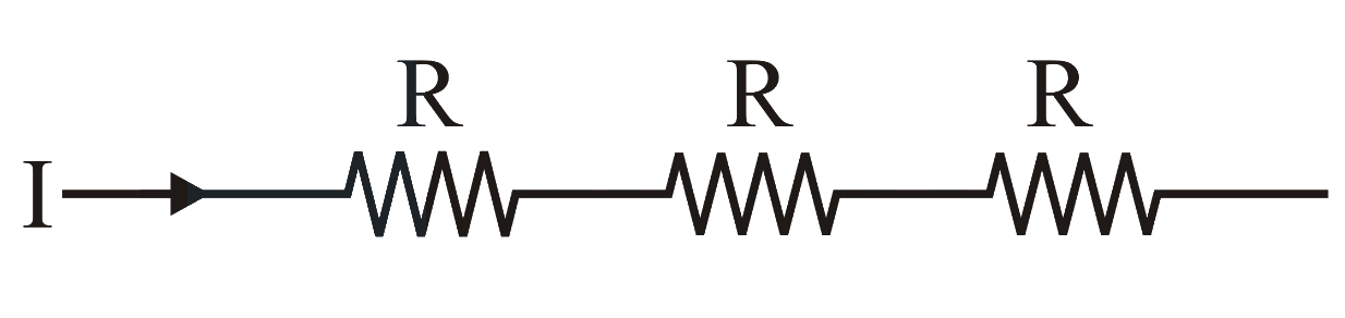 JEE Main/MCQ/Medium/Electric Power and Heating Effect of Current/With diagram
- 239Two identical heater filaments are connected first in parallel and then in series. At the same applied voltage, the ratio of heat produced in same time for parallel to series will be:JEE Main/MCQ/Medium/Electric Power and Heating Effect of Current
- 240The amount of thermal energy is developed by a resistor in when a current of is passed through it. If the current is increased to , the thermal energy developed by the resistor in will beJEE Main/MCQ/Medium/Electric Power and Heating Effect of Current
- 241Ratio of thermal energy released in two resistor and connected in parallel in an electric circuit is :JEE Main/MCQ/Medium/Electric Power and Heating Effect of Current
- 242Two coils require minutes and minutes respectively to produce same amount of heat energy when connected separately to the same source. If they are connected in parallel arrangement to the same source; the time required to produce same amount of heat by the combination of coils, will be _____ .JEE Main/Numerical/Medium/Electric Power and Heating Effect of Current
- 243A resistor develops of thermal energy in , when a current of is passed through it. If the current increases to , the energy developed in is _____ .JEE Main/Numerical/Medium/Electric Power and Heating Effect of Current
- 244A steel rod with and of length and area of cross-section is heated from to without being allowed to extend. The tension produced in the rod is where the value of is _________.JEE Main/Numerical/Medium/Electric Power and Heating Effect of Current
- 245A resistor dissipates of energy in when a current of is passed through it. Now, when the current is doubled, the amount of thermal energy dissipated in is _____________ JEE Main/Numerical/Medium/Electric Power and Heating Effect of Current
- 246An electric bulb of at is used in a circuit having a supply. Calculate the resistance to be connected in series with the bulb so that the power delivered by the bulb is .JEE Main/MCQ/Medium/Electric Power and Heating Effect of Current
- 247An electric bulb rated as at is used in a circuit having supply. The resistance that must be put in series with the bulb so that the bulb delivers the same power is ______ .JEE Main/Numerical/Medium/Electric Power and Heating Effect of Current
- 248The energy dissipated by a resistor is in , when an electric current of flows through it. The resistance is ________. (Round off to the Nearest Integer)JEE Main/Numerical/Medium/Electric Power and Heating Effect of Current
- 249A resistor develops of thermal energy in when a current of is passed through it. If the current is increased from to , what will be the energy developed in .JEE Main/MCQ/Medium/Electric Power and Heating Effect of Current
- 250An electrical power line, having a total resistance of delivers at . The efficiency of the transmission line is approximately :JEE Main/MCQ/Medium/Electric Power and Heating Effect of Current
- 251Model a torch battery of length to be made up of a thin cylindrical bar of radius and a concentric thin cylindrical shell of radius filled in between with an electrolyte of resistivity (see figure). If the battery is connected to a resistance of value , the maximum Joule heating in will take place for :
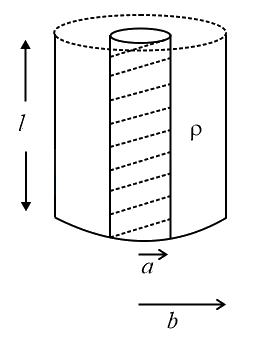 JEE Main/MCQ/Medium/Electric Power and Heating Effect of Current/With diagram
- 252An elliptical loop having resistance , of semi major axis , and semi minor axis is placed in a magnetic field as shown in the figure. If the loop is rotated about the -axis with angular frequency , the average power loss in the loop due to Joule heating is :
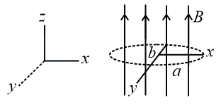 JEE Main/MCQ/Medium/Electric Power and Heating Effect of Current/With diagram
- 253In a building there are bulbs of , bulbs of small fans of and heaters of . The voltage of electric main supply is . The minimum fuse capacity (rated value) of the building will be:JEE Main/MCQ/Medium/Electric Power and Heating Effect of Current
- 254A cell of internal resistance drives current through an external resistance The power delivered by the cell to the external resistance will be maximum when:JEE Main/MCQ/Medium/Electric Power and Heating Effect of Current
- 255Two electric bulbs, rated at and are connected in series across a voltage source. If the and bulbs draw powers and respectively, then:JEE Main/MCQ/Medium/Electric Power and Heating Effect of Current
- 256Two equal resistances when connected in series to a battery, consume electric power of . If these resistance are now connected in parallel combination to the same battery, the electric power consumed will be :JEE Main/MCQ/Medium/Electric Power and Heating Effect of Current
- 257A current of was passed through an unknown resistor which dissipated a power of Dissipated power when an ideal power supply of is connected across it is:JEE Main/MCQ/Medium/Electric Power and Heating Effect of Current
- 258A heating element has a resistance of at room temperature. When it is connected to a supply of , a steady current of passes in it and temperature is more than the room temperature. The temperature coefficient of resistance of the heating element isJEE Main/MCQ/Medium/Electric Power and Heating Effect of Current
- 259A constant voltage is applied between two ends of a metallic wire. If the length is halved and the radius of the wire is doubled, the rate of heat developed in the wire will be:JEE Main/MCQ/Medium/Electric Power and Heating Effect of Current
- 260The figure shows three circuits and which are connected to a battery. If the powers dissipated by the configurations and are and respectively, then -
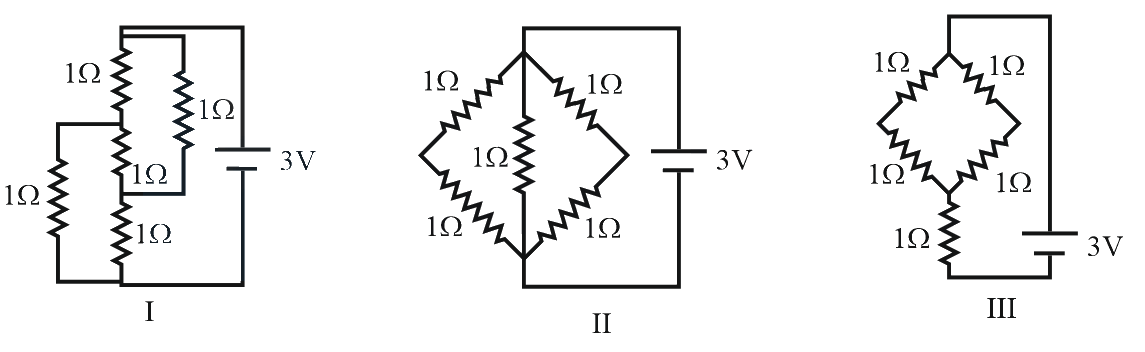 JEE Main/MCQ/Medium/Electric Power and Heating Effect of Current/With diagram
- 261
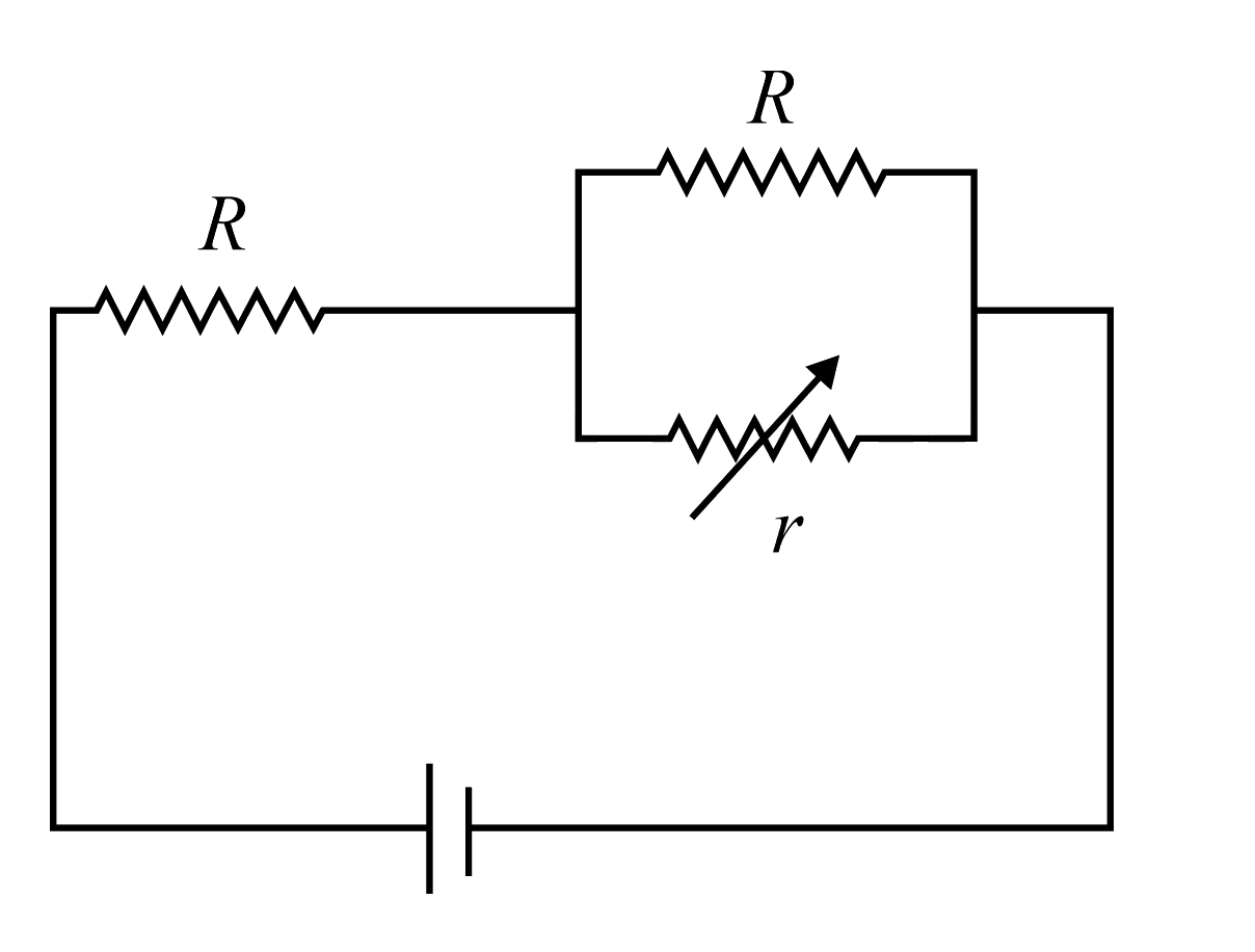
In the circuit shown, the resistance r is a variable resistance. If for , the heat generation in r is maximum then the value of isJEE Main/MCQ/Medium/Electric Power and Heating Effect of Current/With diagram - 262In a large building, there are 15 bulbs of 40 W, 5 bulbs of 100 W, 5 fans of 80 W and 1 heater of 1 kW. The voltage of the electric mains is 220 V. The minimum capacity of the main fuse of the building will be:JEE Main/MCQ/Medium/Electric Power and Heating Effect of Current
- 263Which of the four resistances and generate the greatest amount of heat when a current flows from A to B ?
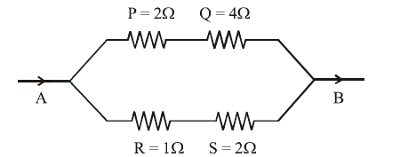 JEE Main/MCQ/Medium/Electric Power and Heating Effect of Current/With diagram
- 264A volt battery is connected to two light bulbs as shown in figure. Light bulb 1 has resistance 3 ohm while light bulb 2 has resistance . Battery has negligible internal resistance. Which bulb will glow brighter?
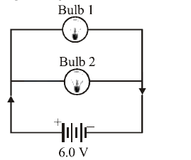 JEE Main/MCQ/Medium/Electric Power and Heating Effect of Current/With diagram
- 265Three resistors of and are connected in parallel and the combination is connected in series with a battery of internal resistance. The rate of Joule heating in the resistor isJEE Main/MCQ/Medium/Electric Power and Heating Effect of Current
- 266Two electric bulbs marked and are connected in series to a supply.
Which of the bulbs will fuse?JEE Main/MCQ/Medium/Electric Power and Heating Effect of Current - 267An electric bulb is rated 220 volt watt. The power consumed by it when operated on 110 volt will beJEE Main/MCQ/Medium/Electric Power and Heating Effect of Current
- 268The resistance of hot tungsten filament is about 10 times the cold resistance. What will be the resistance of and lamp when not in use?JEE Main/MCQ/Medium/Electric Power and Heating Effect of Current
- 269A heater coil is cut into two equal parts and only one part is now used in the heater. The heat generated will now beJEE Main/MCQ/Medium/Electric Power and Heating Effect of Current
- 270The electrochemical equivalent of a metal is per coulomb. The mass of the metal liberated at the cathode when a 3 A current is passed for 2 seconds will beJEE Main/MCQ/Medium/Electric Power and Heating Effect of Current
- 271A 220 volt, 1000 watt bulb is connected across a 110 volt mains supply. The power consumed will beJEE Main/MCQ/Medium/Electric Power and Heating Effect of Current
- 272If in the circuit, power dissipation is , then is
 JEE Main/MCQ/Medium/Electric Power and Heating Effect of Current/With diagram
- 273If a current is passed through a spring then the spring willJEE Main/MCQ/Medium/Electric Power and Heating Effect of Current
- 274A wire when connected to mains supply has power dissipation . Now the wire is cut into two equal pieces which are connected in parallel to the same supply. Power dissipation in this case is Then isJEE Main/MCQ/Medium/Electric Power and Heating Effect of Current
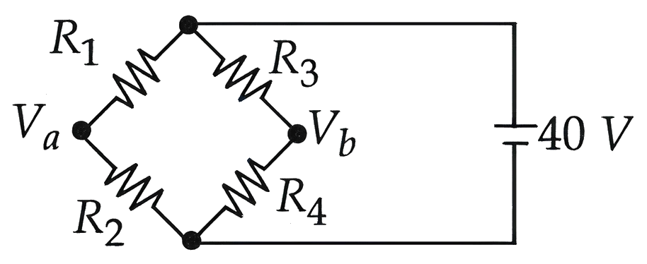
- 275A Wheatstone bridge is initially at room temperature and all arms of the bridge have same value of resistances . When resistance is heated to some temperature, its resistance value has gone up by . The potential difference (after is heated) is V.
 JEE Main/MCQ/Medium/Wheatstone Bridge/With diagram
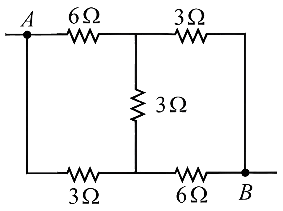
- 276The equivalent resistance between the points and in the following circuit is . The value of is .
 JEE Main/Numerical/Medium/Wheatstone Bridge/With diagram
- 277In a meter bridge experiment to determine the value of unknown resistance, first the resistances and are connected in the left and right gaps of the bridge and the null point is obtained at a distance from the left. Now when an unknown resistance is connected in parallel to resistance, the null point is shifted by 10 cm to the right of wire. The value of unknown resistance is .JEE Main/Numerical/Medium/Wheatstone Bridge
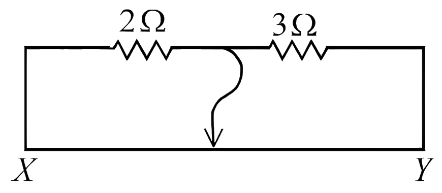
- 278Two resistors and are connected in the gaps of bridge as shown in figure. The null point is obtained with the contact of jockey at some point on wire . When an unknown resistor is connected in parallel with resistor, the null point is shifted by 22.5 cm toward . The resistance of unknown resistor is .
 JEE Main/MCQ/Medium/Wheatstone Bridge/With diagram
- 279A meter bridge with two resistances and as shown in figure was balanced (null point) at 40 cm from the point . The null point changed to 50 cm from the point , when resistance is connected in parallel to . The values of resistances and are .
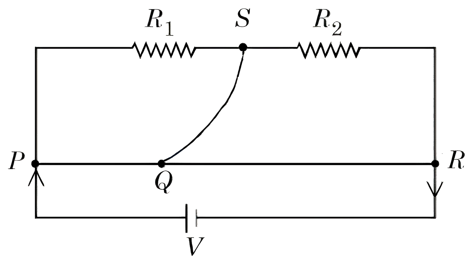 JEE Main/MCQ/Medium/Wheatstone Bridge/With diagram
- 280The heat generated in 1 minute between points and in the given circuit, when a battery of 9 V with internal resistance of is connected across these points is J.
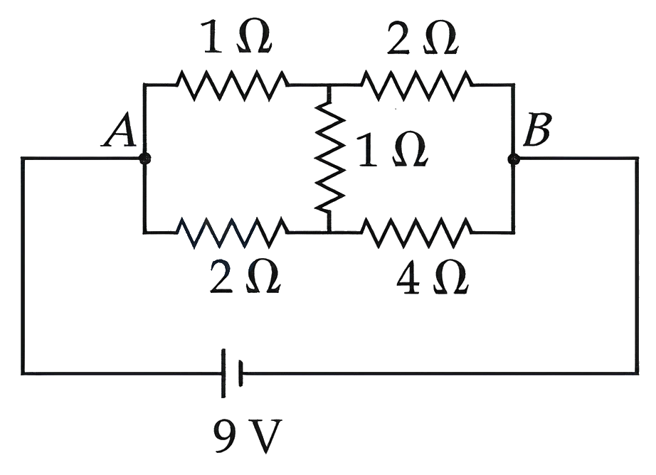 JEE Main/Numerical/Medium/Wheatstone Bridge/With diagram
- 281A wire of resistance is bent into a triangular pyramid as shown in figure with each segment having same length. The resistance between points and is . The value of is :
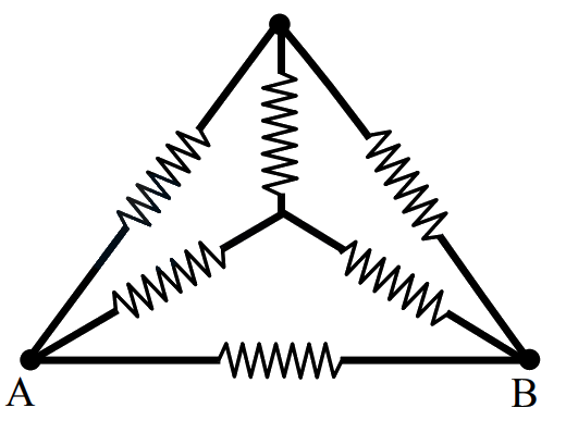 JEE Main/MCQ/Medium/Wheatstone Bridge/With diagram
- 282The value of unknown resistance for which the potential difference between and will be zero in the arrangement shown, is :
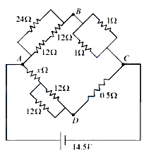 JEE Main/MCQ/Medium/Wheatstone Bridge/With diagram
- 283In a metre-bridge when a resistance in the left gap is and unknown resistance in the right gap, the balance length is found to be On shunting the unknown resistance with the balance length changes by:JEE Main/MCQ/Medium/Wheatstone Bridge
- 284The resistance per centimeter of a meter bridge wire is , with resistance in left gap. Balancing length from left end is at with resistance in right gap. Now the wire is replaced by another wire of resistance per centimeter. The new balancing length for same settings will be atJEE Main/MCQ/Medium/Wheatstone Bridge
- 285Wheatstone bridge principle is used to measure the specific resistance of given wire, having length , radius . If is the resistance of wire, then specific resistance is : . If the length of the wire gets doubled then the value of specific resistance will be :JEE Main/MCQ/Medium/Wheatstone Bridge
- 286A wire of length and radius connected across the right gap of a meter bridge. When a resistance of is connected on the left gap by using a resistance box, the balance length is found to be at from the left end. If the resistivity of the wire is , then value of is :JEE Main/MCQ/Medium/Wheatstone Bridge
- 287In meter bridge experiment for measuring unknown resistance '', the null point is obtained at a distance from the left side as shown at point . If is , then the value of unknown resistance '' will be _____ .
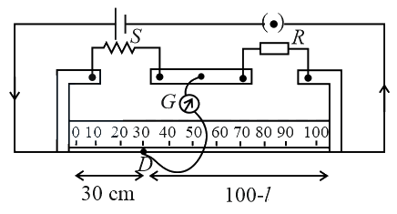 JEE Main/Numerical/Medium/Wheatstone Bridge/With diagram
- 288A battery of is connected to the circuit as shown below. The current drawn from the battery is
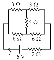 JEE Main/MCQ/Medium/Wheatstone Bridge/With diagram
- 289Resistance are connected in a meter bridge circuit as shown in the figure. The balancing length is . Now an unknown resistance is connected in series with and new balancing length is found to be measured from the same end. Then the value of will be _____ .
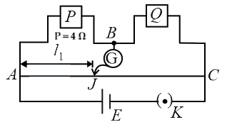 JEE Main/Numerical/Medium/Wheatstone Bridge/With diagram
- 290The current in the given circuit will be
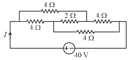 JEE Main/MCQ/Medium/Wheatstone Bridge/With diagram
- 291Current measured by the ammeter in the reported circuit when no current flows through resistance, will be _____ .
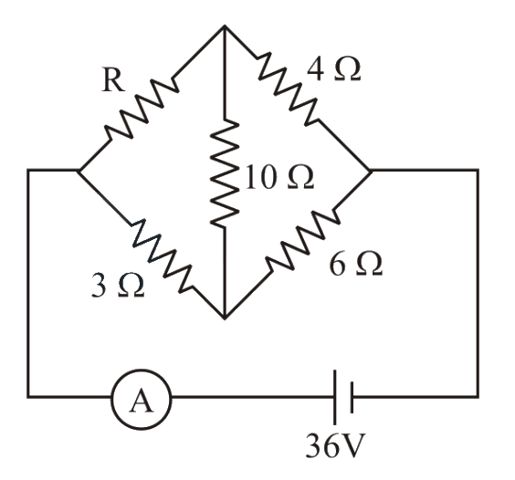 JEE Main/Numerical/Medium/Wheatstone Bridge/With diagram
- 292A meter bridge setup is shown in the figure. It is used to determine an unknown resistance using a given resistor of . The galvanometer shows null defection when tapping key is at mark from end . If the end correction for end is , then the determined value of will be .
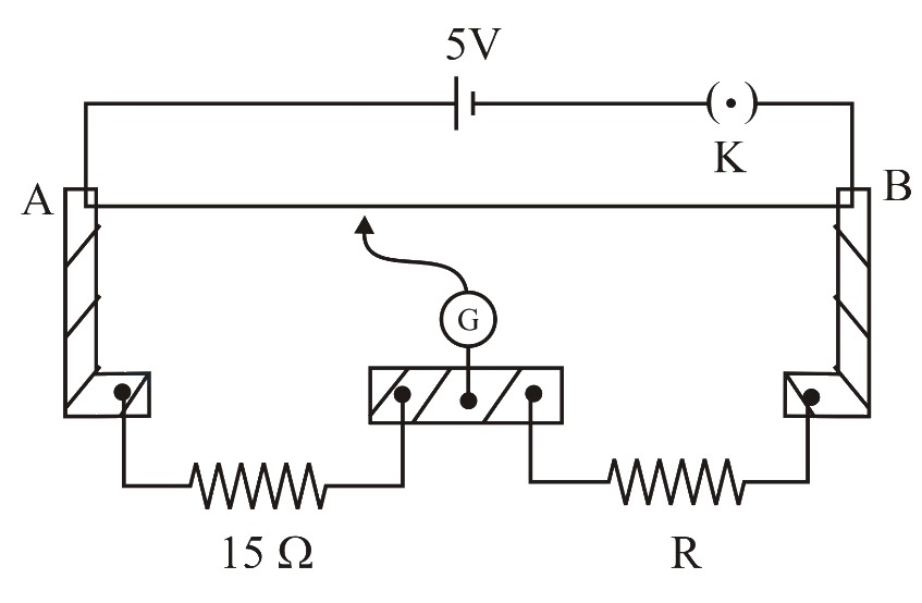 JEE Main/Numerical/Medium/Wheatstone Bridge/With diagram
- 293Consider a long wire as shown in the figure. The galvanometer jockey is placed at on at a distance from . The galvanometer shows zero deflection.
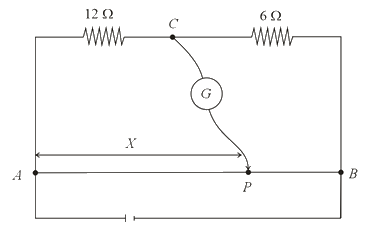
The value of , to the nearest integer, isJEE Main/Numerical/Medium/Wheatstone Bridge/With diagram - 294The four arms of a Wheatstone bridge have resistances as shown in the figure. A galvanometer of resistance is connected across BD. Calculate the current through the galvanometer when a potential difference of is maintained across AC.
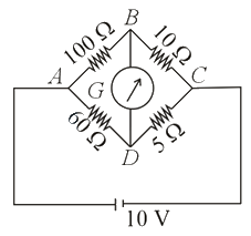 JEE Main/MCQ/Medium/Wheatstone Bridge/With diagram
- 295Five equal resistances are connected in a network as shown in figure. The net resistance between the points and is :
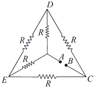 JEE Main/MCQ/Medium/Wheatstone Bridge/With diagram
- 296The value of current flowing from to in the circuit diagram is :
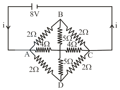 JEE Main/MCQ/Medium/Wheatstone Bridge/With diagram
- 297In a meter bridge experiment is a standard resistance. is a resistance wire. It is found that balancing length is If is replaced by a wire of hall length and half diameter that of of same material, then the balancing distance (in ) will now be ______________.
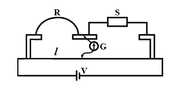 JEE Main/Numerical/Medium/Wheatstone Bridge/With diagram
- 298Four resistances of and respectively in cyclic order to form Wheatstone’s network. The resistance that is to be connected in parallel with the resistance of to balance the network is ______________ JEE Main/Numerical/Medium/Wheatstone Bridge
- 299In a Wheatstone bridge (see fig.), Resistances and are approximatelyequal. When , the bridge is balanced. On interchanging and , the value of for balance, is . The value of is close to
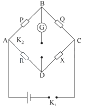 JEE Main/MCQ/Medium/Wheatstone Bridge/With diagram
- 300The Wheatstone bridge shown in the figure below, gets balanced when the carbon resistor used as has the colour code (orange, red, brown). The resistors and are and , respectively. Assuming that the colour code for the carbon resistors gives their accurate values, the colour code for the carbon resistor, used as , would be
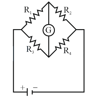 JEE Main/MCQ/Medium/Wheatstone Bridge/With diagram
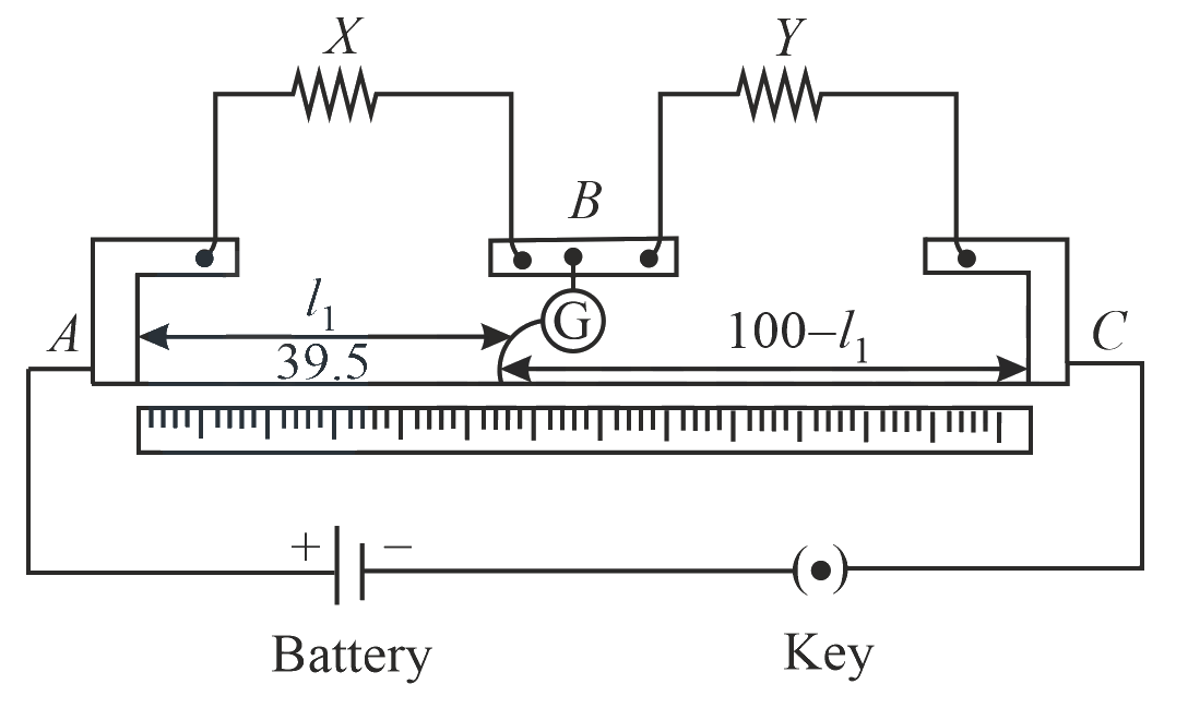
- 301In a meter bridge as shown in the figure, it is given that resistance and that the balance is obtained at a distance from end (by jockey ). After interchanging the resistances and a new balance point is found at a distance from end . What are the values of (in ) and ?
 JEE Main/MCQ/Medium/Wheatstone Bridge/With diagram
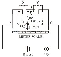
- 302In a meter bridge, as shown in the figure, it is given that resistance and that the balance is obtained at a distance from end (by jockey J). After interchanging the resistances and , a new balance point is found at a distance from end . What are the values of and ?
 JEE Main/MCQ/Medium/Wheatstone Bridge/With diagram
- 303On interchanging the resistances, the balance point of a meter bridge shifts to the left by . The resistance of their series combination is . How much was the resistance on the left slot before interchanging the resistances?JEE Main/MCQ/Medium/Wheatstone Bridge
- 304In a meter bridge experiment resistances are connected as shown in the figure. Initially resistance and the neutral point is at from . Now an unknown resistance is connected in series to and the new position of the neutral point is at from . The value of unknown resistance is -
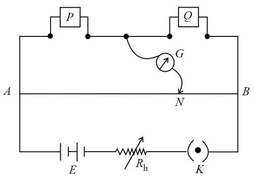 JEE Main/MCQ/Medium/Wheatstone Bridge/With diagram
- 305Which of the following statements is false?JEE Main/MCQ/Medium/Wheatstone Bridge
- 306In a metre bridge experiment null point is obtained at from one end of the wire when resistance is balanced against another resistance . If , then the new position of the null point from the same end, if one decides to balance a resistance of against , will be close to :JEE Main/MCQ/Medium/Wheatstone Bridge
- 307In a sensitive meter bridge apparatus the bridge wire should possessJEE Main/MCQ/Medium/Wheatstone Bridge
- 308In a Wheatstone's bridge, there resistances and connected in the three arms and the fourth arm is formed by two resistances and connected in parallel. The condition for bridge to be balanced will beJEE Main/MCQ/Medium/Wheatstone Bridge
- 309In a metre bridge experiment null point is obtained at from one end of the wire when resistance is balanced against another resistance . If , then where will be the new position of the null point from the same end, if one decides to balance a resistance of against Y?JEE Main/MCQ/Medium/Wheatstone Bridge
- 310A moving coil of galvanometer when shunted with resistance gives a full scale deflection for a current of mA. When a resistance of is connected in series it gives a full scale deflection for V potential applied on it. The value of resistance of galvanometer coil is __________ .JEE Main/Numerical/Medium/Electric Instruments
- 311A voltmeter with internal resistance of can be used to measure upto V. In order to increase its measuring range to V, the required modification is to _____.JEE Main/MCQ/Medium/Electric Instruments
- 312In the potentiometer, when the cell in the secondary circuit is shunted with resistance, the balance is obtained at the length 120 cm of wire. Now when the same cell is shunted with resistance, the balance is shifted to a length of 180 cm. The internal resistance of cell is JEE Main/MCQ/Medium/Electric Instruments
- 313A moving coil galvanometer of resistance shows a full scale deflection for a current of 1 mA. The value of resistance required to convert this galvanometer into an ammeter, showing full scale deflection for a current of 5 mA, is JEE Main/MCQ/Medium/Electric Instruments
- 314Two resistors of each are connected in series with a 9 V battery. A voltmeter of resistance is connected to measure the voltage drop across one of the resistors. The voltmeter reading is V.JEE Main/MCQ/Medium/Electric Instruments
- 315To compare EMF of two cells using potentiometer the balancing lengths obtained are 200 cm and 150 cm. The least count of scale is 1 cm. The percentage error in the ratio of EMFs is .JEE Main/MCQ/Medium/Electric Instruments
- 316A battery with EMF and internal resistance is connected across a resistance . The power consumption in will be maximum when :JEE Main/MCQ/Medium/Electric Instruments
- 317The total length of potentiometer wire AB is 50 cm in the arrangement as shown in figure. If is the point where the galvanometer shows zero reading then the length is cm.
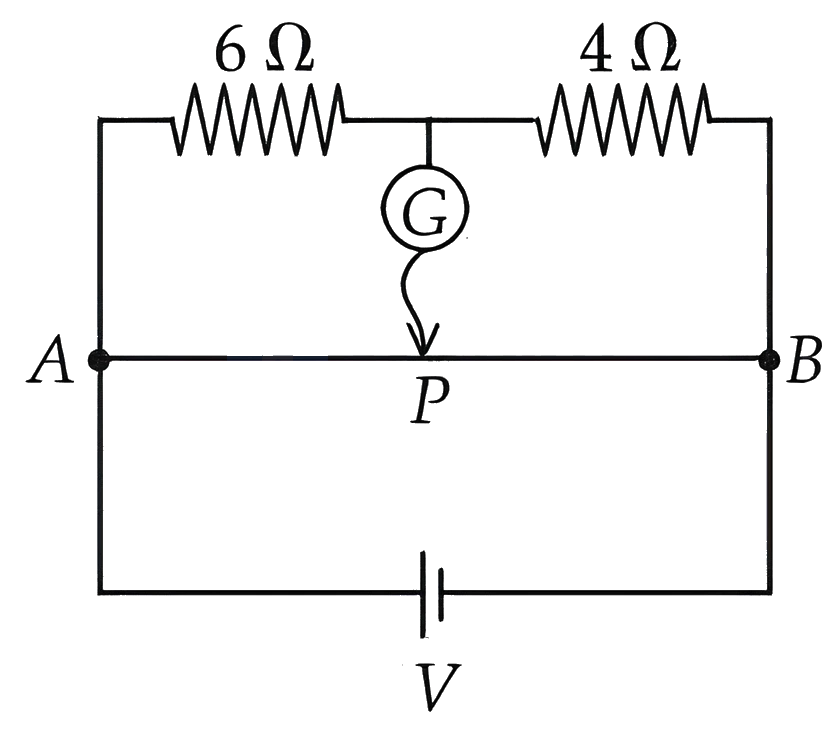 JEE Main/MCQ/Medium/Electric Instruments/With diagram
- 318In the figure shown below, a resistance of is connected in series to an ammeter A of resistance . A shunt resistance of is connected in parallel with the ammeter. The reading of the ammeter is _____ mA.
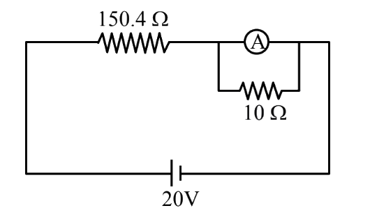 JEE Main/Numerical/Medium/Electric Instruments/With diagram
- 319A galvanometer having a coil of resistance need 20 mA of current for full-scale deflection. If a maximum current of 3 A is to be measured using this galvanometer, the resistance of the shunt to be added to the galvanometer should be , where is
OptionsJEE Main/MCQ/Medium/Electric Instruments - 320
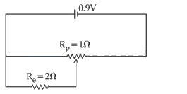
Sliding contact of a potentiometer is in the middle of the potentiometer wire having resistance as shown in the figure. An external resistance of is connected via the sliding contact. The electric current in the circuit is :JEE Main/MCQ/Medium/Electric Instruments/With diagram - 321A galvanmeter has a coil of resistance with a full scale deflection at . The value of resistance to be added to use it as an ammeter of range is ;JEE Main/MCQ/Medium/Electric Instruments
- 322In the given figure an ammeter A consists of a coil connected in parallel to a shunt. The reading of the ammeter is
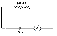 JEE Main/Numerical/Medium/Electric Instruments/With diagram
- 323A galvanometer of resistance when connected in series with measures a voltage of upto . The value of resistance required to convert the galvanometer into ammeter to read upto is . The value of is :JEE Main/MCQ/Medium/Electric Instruments
- 324In the experiment to determine the galvanometer resistance by half-deflection method, the plot of vs the resistance of the resistance box is shown in the figure. The figure of merit of the galvanometer is _____ division. [The source has emf 2V]
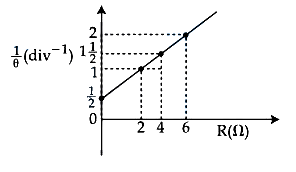 JEE Main/Numerical/Medium/Electric Instruments/With diagram
- 325To measure the internal resistance of a battery, potentiometer is used. For , the balance point is observed at and for the balance point is observed at . The internal resistance of the battery is approximately :JEE Main/MCQ/Medium/Electric Instruments
- 326To measure the temperature coefficient of resistivity of a semiconductor, an electrical arrangement shown in the figure is prepared. The arm is made up of the semiconductor. The experiment is being conducted at and resistance of the semiconductor arm is . Arm is cooled at a constant rate of . If the galvanometer shows no deflection after then is:
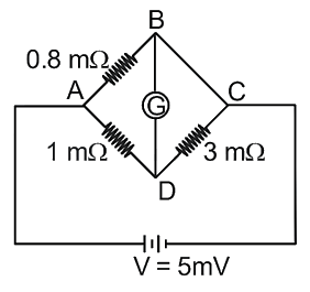 JEE Main/MCQ/Medium/Electric Instruments/With diagram
- 327In an ammeter, of the main current passes through the galvanometer. If resistance of the galvanometer is the resistance of ammeter will be:JEE Main/MCQ/Medium/Electric Instruments
- 328A galvanometer has a resistance of and it allows maximum current of . It can be converted into voltmeter to measure upto by connecting in series a resistor of resistance.JEE Main/MCQ/Medium/Electric Instruments
- 329The reading in the ideal voltmeter shown in the given circuit diagram is:
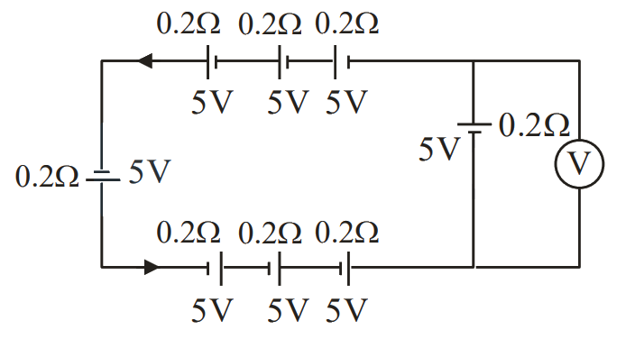 JEE Main/MCQ/Medium/Electric Instruments/With diagram
- 330Two resistance of and are connected in series with a battery of and negligible internal resistance. A voltmeter is used to measure voltage across resistance, which gives reading as . The resistance of voltmeter must be _______ .JEE Main/Numerical/Medium/Electric Instruments
- 331The deflection in moving coil galvanometer falls from divisions to division when a shunt of is applied. The resistance of galvanometer coil will be:JEE Main/MCQ/Medium/Electric Instruments
- 332A galvanometer having coil resistance shows a full scale deflection for a current of . For it to measure a current of , the value of the shunt should be:JEE Main/MCQ/Medium/Electric Instruments
- 333Three voltmeters, all having different internal resistances are joined as shown in figure. When some potential difference is applied across and , their readings are and . Choose the correct option.
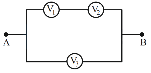 JEE Main/MCQ/Medium/Electric Instruments/With diagram
- 334A current of deflects the coil of a moving coil galvanometer through . The current to cause deflection through radian isJEE Main/MCQ/Medium/Electric Instruments
- 335For designing a voltmeter of range and an ammeter of range using a galvanometer which has a coil of resistance showing a full scale deflection for as in figure.
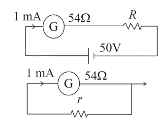
(A) for voltmeter
(B) for ammeter
(C) for ammeter
(D) for voltmeter
(E) for voltmeter
Choose the correct answer from the options given below:JEE Main/MCQ/Medium/Electric Instruments/With diagram - 336When a resistance of is shunted with a moving coil galvanometer, it shows a full scale deflection for a current of however when resistance is connected with it in series, it gives full scale deflection for volt. The resistance of galvanometer is_________\Omega .JEE Main/Numerical/Medium/Electric Instruments
- 337The current sensitivity of moving coil galvanometer is increased by . This increase is achieved only changing in the number of turns of coils and area of cross section of the wire while keeping the resistance of galvanometer coil constant. The percentage change in the voltage sensitivity will be:JEE Main/MCQ/Medium/Electric Instruments
- 338In this figure the resistance of the coil of galvanometer is . The emf of the cell is . The ratio of potential difference across and is
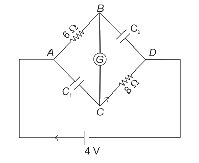 JEE Main/MCQ/Medium/Electric Instruments/With diagram
- 339As shown in the figure the voltmeter reads across resistor. The resistance of the voltmeter is _____
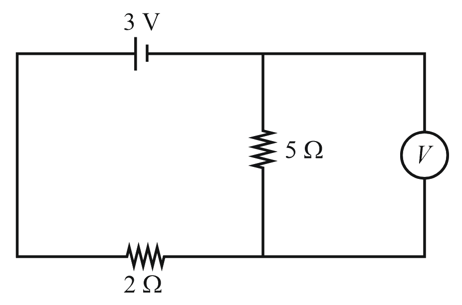 JEE Main/Numerical/Medium/Electric Instruments/With diagram
- 340A student is provided with a variable voltage source , a test resistor , two identical galvanometers and and two additional resistors, and . For conducting an experiment to verify ohm's law, the most suitable circuit is:JEE Main/MCQ/Medium/Electric Instruments
- 341The number of turns of the coil of a moving coil galvanometer is increased in order to increase current sensitivity by . The percentage change in voltage sensitivity of the galvanometer will be :JEE Main/MCQ/Medium/Electric Instruments
- 342In the given figure of meter bridge experiment, the balancing length corresponding to null deflection of the galvanometer is . The balancing length, if the radius of the wire is doubled, will be _____ .
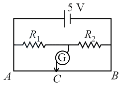 JEE Main/Numerical/Medium/Electric Instruments/With diagram
- 343A galvanometer is shunted by a resistance of . The percentage of the total current which passes through the galvanometer isJEE Main/MCQ/Medium/Electric Instruments
- 344If represents the actual number of deflections in a converted galvanometer of resistance and shunt resistance . Then the total current when its figure of merit is will beJEE Main/MCQ/Medium/Electric Instruments
- 345A teacher in his physics laboratory allotted an experiment to determine the resistance a galvanometer. Students took the observations for deflection in the galvanometer. Which of the below is true for measuring value of ?JEE Main/MCQ/Medium/Electric Instruments
- 346Consider a galvanometer shunted with resistance and of current passes through it. What is the resistance of the given galvanometer?JEE Main/MCQ/Medium/Electric Instruments
- 347For full scale deflection of total divisions, voltage is required in galvanometer. The resistance of galvanometer if its current sensitivity is will be:JEE Main/MCQ/Medium/Electric Instruments
- 348A circuit to verify Ohm's law uses ammeter and voltmeter in series or parallel connected corrected correctly to the resistor. In the circuit :JEE Main/MCQ/Medium/Electric Instruments
- 349A galvanometer is used in laboratory for detecting the null point in electrical experiments. If, on passing a current of it produces a deflection of , its figure of merit is close to :JEE Main/MCQ/Medium/Electric Instruments
- 350A galvanometer of resistance is converted into a voltameter of range by connecting a resistance in series with it. The additional resistance that should be connected in series with to increase the range of the voltmeter to will be :JEE Main/MCQ/Medium/Electric Instruments
- 351A galvanometer coil has 500 turns and each turn has an average area of . If a torque of is required to keep this coil parallel to a magnetic field when a current of is flowing through it, the strength of the field (in ) is _________ .JEE Main/Numerical/Medium/Electric Instruments
- 352Which of the following will NOT be observed when a multimeter (operating in resistance measuring mode) probes connected across a component, are just reversed?JEE Main/MCQ/Medium/Electric Instruments
- 353A galvanometer having a coil resistance gives a full scale deflection when a current of is passed through it. What is the value of the resistance which can convert this galvanometer into a voltmeter given full scale deflection for a potential difference of JEE Main/MCQ/Medium/Electric Instruments
- 354A moving coil galvanometer, having a resistance produces full scale deflection when a current flows through it. This galvanometer can be converted into (i) an ammeter of range 0 to by connecting a shunt resistance to it and (ii) into a voltmeter of range 0 to by connecting a series resistance to it. Then,JEE Main/MCQ/Medium/Electric Instruments
- 355A galvanometer of resistance has divisions on its scale and has sensitivity of . It is to be converted to voltmeter with three ranges, of and The appropriate circuit to do so is:JEE Main/MCQ/Medium/Electric Instruments
- 356A moving coil galvanometer allows a full scale current of . A series resistance of is required to convert the galvanometer into a voltmeter of range . Therefore, the value of shunt resistance required to convert the above galvanometer into an ammeter of range is:JEE Main/MCQ/Medium/Electric Instruments
- 357The resistance of a galvanometer is and the maximum current which can be passed through it is What resistance must be connected to it in order to convert it into an ammeter of range JEE Main/MCQ/Medium/Electric Instruments
- 358A moving coil galvanometer has resistance and it indicates full deflection at current. A voltmeter is made using this galvanometer and a resistance. The maximum voltage, that can be measured using this voltmeter, will be close to:JEE Main/MCQ/Medium/Electric Instruments
- 359A galvanometer, whose resistance is , has divisions in it. When a current of A passes through it, its needle (pointer) deflects by one division. To use this galvanometer as a voltmeter of range it should be connected to a resistance of:JEE Main/MCQ/Medium/Electric Instruments
- 360The galvanometer deflection, when key is closed but is open, equals (see figure). On closing also and adjusting to the deflection in galvanometer becomes The resistance of the galvanometer is, then, given by [Neglect the internal resistance of battery]:
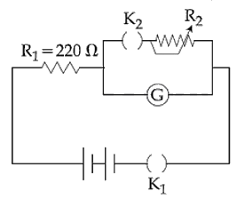 JEE Main/MCQ/Medium/Electric Instruments/With diagram
- 361A galvanometer having a resistance of and 30 division on both sides has figure of merit 0.005 ampere/ division. The resistance that should be connected in series such that it can be used as a voltmeter upto 15 volt, is:JEE Main/MCQ/Medium/Electric Instruments
- 362In a circuit for finding the resistance of a galvanometer by half deflection method, a battery and a high resistance of are used. The figure of merit of the galvanometer is . In the absence of shunt resistance, the galvanometer produces a deflection of divisions when current flows in the circuit. The value of the shunt resistance that can cause the deflection of , is closest to:JEE Main/MCQ/Medium/Electric Instruments
- 363A galvanometer with its coil resistance requires a current of for its full deflection. In order to construct an ammeter to read up to a current of the approximate value of the shunt resistance should be:JEE Main/MCQ/Medium/Electric Instruments
- 364When a current of is passed through a galvanometer having a coil of resistance , it shows full-scale deflection. The value of the resistance to be put in series with the galvanometer to convert it into a voltmeter of range is:JEE Main/MCQ/Medium/Electric Instruments
- 365A galvanometer has a 50 division scale. Battery has no internal resistance. It is found that there is deflection of 40 divisions when Deflection becomes 20 divisions when resistance taken from resistance box is 4900 Ω. Then we can conclude :
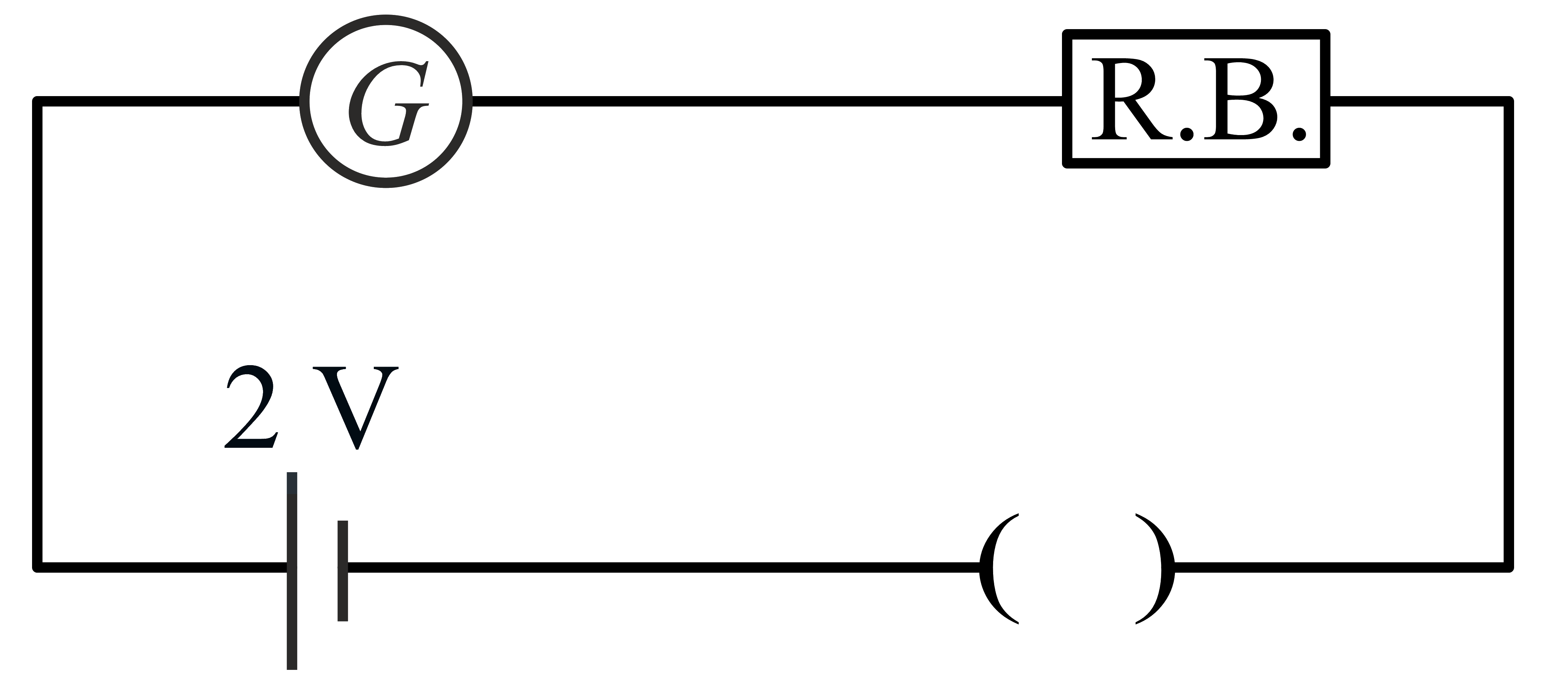
Note: This question is awarded as the bonus. Now the question is corrected.JEE Main/MCQ/Medium/Electric Instruments/With diagram - 366A resistance is connected to a battery of . A galvanometer of resistance is to be used as an ammeter to measure current through the resistance, for this a resistance is connected to the galvanometer. Which of the following connections should be employed if the measured current is with in of the current without the ammeter in the circuit?JEE Main/MCQ/Medium/Electric Instruments
- 367To know the resistance of a galvanometer by half deflection method, a battery of emf and resistance is used to deflect the galvanometer by angle . If a shunt of resistance is needed to get half deflection the , and are related by the equation:JEE Main/MCQ/Medium/Electric Instruments
- 368A galvanometer having a coil resistance of gives a full scale deflection, when a current of is passed through it. The value of the resistance, which can convert this galvanometer into ammeter giving a full scale deflection for a current of , is:JEE Main/MCQ/Medium/Electric Instruments
- 369A battery with internal resistance and a battery with internal resistance are connected in parallel to a voltmeter (see figure). The reading in the voltmeter will be close to:
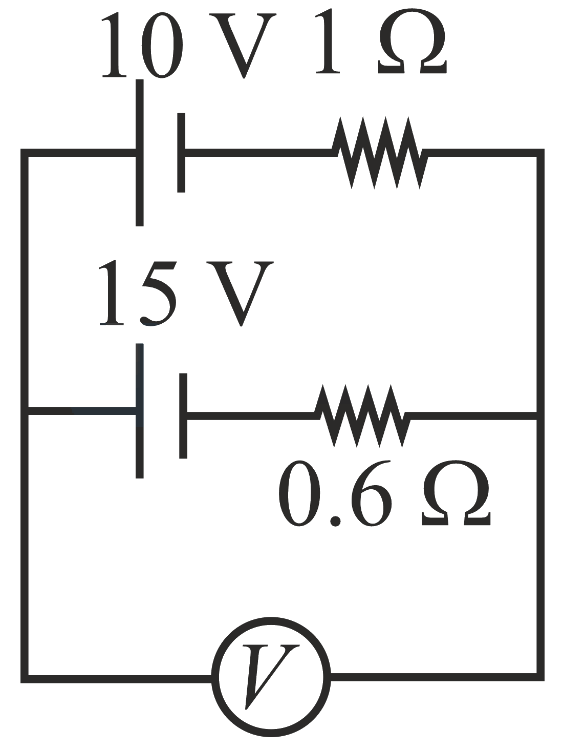 JEE Main/MCQ/Medium/Electric Instruments/With diagram
- 370
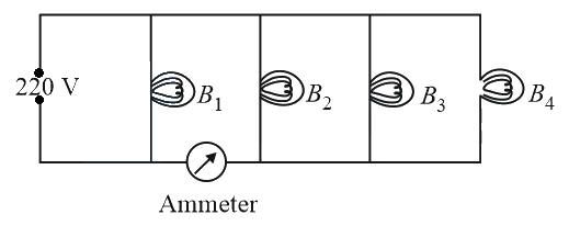
Four bulbs , , and of each are connected to main as shown in the figure. The reading in an ideal ammeter will beJEE Main/MCQ/Medium/Electric Instruments/With diagram - 371In the experiment of calibration of voltmeter, a standard cell of e.m.f. volt is balanced against of potential wire. The potential difference across the ends of resistance is found to balance against of the wire. The corresponding reading of voltmeter is volt. The error in the reading of volmeter will be:JEE Main/MCQ/Medium/Electric Instruments
- 372In the circuit diagrams (A, B, C and D) shown below, is a high resistance and is a resistance of the order of galvanometer resistance G. The correct circuit, corresponding to the half deflection method for finding the resistance and figure of merit of the galvanometer, is the circuit labelled as:
(a)
(b)
(C)
(d) JEE Main/MCQ/Medium/Electric Instruments/With diagram
- 373To find the resistance of a galvanometer by the half deflection method the following circuit is used with resistances and . The deflection in the galvanometer is d. With the deflection changed to . The galvanometer resistance is approximately:
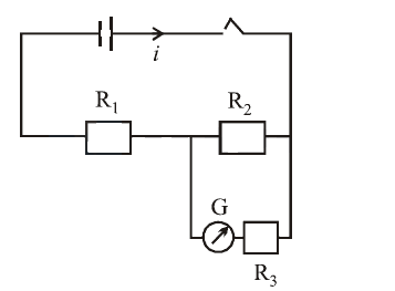 JEE Main/MCQ/Medium/Electric Instruments/With diagram
- 374A shunt of resistance is connected across a galvanometer of resistance. A current of ampere gives full scale deflection in the galvanometer. The current that will give full scale deflection in the absence of the shunt is nearly :JEE Main/MCQ/Medium/Electric Instruments
- 375This question has and . Of the four choices given after the Statements, choose the one that best describes the two Statements.
Higher the range, greater is the resistance of ammeter.
To increase the range of ammeter, additional shunt needs to be used across it.JEE Main/MCQ/Medium/Electric Instruments - 376Two voltameters one of copper and another of silver, are joined in parallel. When a total charge flows through the voltameters, equal amount of metals are deposited. If the electrochemical equivalents of copper and silver are and respectively the charge which flows through the silver voltameter isJEE Main/MCQ/Medium/Electric Instruments
- 377A moving coil galvanometer has 150 equal divisions. Its current sensitivity is 10 divisions per milliampere and voltage sensitivity is 2 divisions per millivolt. In order that each division reads 1 volt, the resistance in ohms needed to be connected in series with the coil will beJEE Main/MCQ/Medium/Electric Instruments
- 378An ammeter reads up to 1 ampere. Its internal resistance is . To increase the range to the value of the required shunt isJEE Main/MCQ/Medium/Electric Instruments
- 379The thermo e.m.f. of a thermo-couple is at room temperature. A galvanometer of 40 ohm resistance, capable of detecting current as low as , is connected with the thermo couple. The smallest temperature difference that can be detected by this sytem isJEE Main/MCQ/Medium/Electric Instruments
- 380If an ammeter is to be used in place of a voltmeter, then we must connect with the ammeter aJEE Main/MCQ/Medium/Electric Instruments
NEET question paper PDF
This chapter includes NEET questions. Open a year to read the full paper, or download the PDF.
Opening paper…
JEE Main question paper PDF
This chapter includes JEE Main questions. Open a shift to read the paper, or download the PDF.
Opening paper…
Other Physics chapters
Electrostatics 311Kinematics 308Ray Optics 295Rotational Motion 280Magnetic Effects & Magnetism 276Atoms & Nuclei 239Gravitation 223Laws of Motion 210Semiconductors 209Dual Nature of Matter 200Oscillations 194Fluid Mechanics 192Wave Optics 191Alternating Current 190Thermodynamics 190Work Energy Power 183Capacitors 180Kinetic Theory 168Electromagnetic Waves 165Electromagnetic Induction 153Units & Dimensions 149Waves 142Center of Mass, Momentum & Collision 130Thermal Properties of Matter 126Mathematics in Physics 121Mechanical Properties of Solids 118Experimental Physics 70Magnetic Properties of Matter 57Modern Physics 5
Stuck on a Current Electricity question from your book?
Snap it and get a whiteboard video that solves it step by step. Your first video needs no login.